15
(5) Positioning Modules
Precautions to be followed when the machinery conforming to the
EMC Directive is configured using the A1SD75P-S3 are
described below.
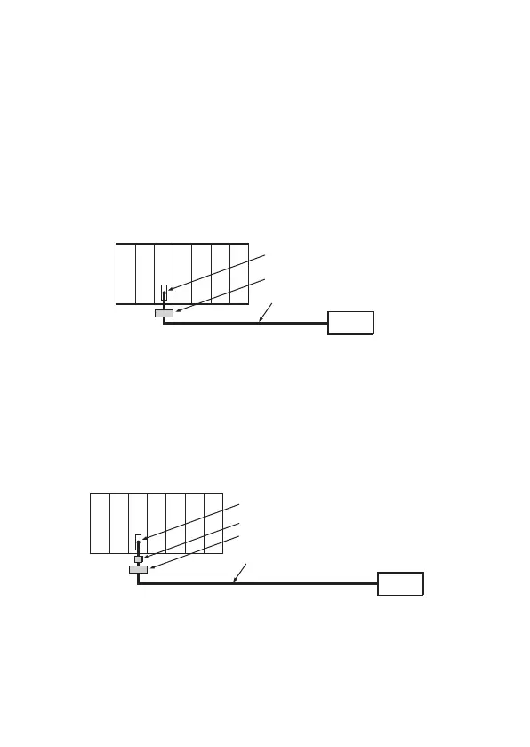
(a) When wiring with a 2 m (6.56 ft.) or less cable
• Ground the shield section of the external wiring cable with
the cable clamp.
(Ground the shield at the closest location to the A1SD75
external wiring connector.)
• Wire the external wiring cable to the drive unit and external
device with the shortest practicable length of cable.
• Install the drive unit in the same panel.
(b) When wiring with cable that exceeds 2 m (6.56 ft.), but is 10 m
(32.81 ft.) or less
• Ground the shield section of the external wiring cable with
the cable clamp.
(Ground the shield at the closest location to the A1SD75
external wiring connector.)
• Install a ferrite core.
• Wire the external wiring cable to the drive unit and external
device with the shortest practicable length of cable.
Cable clamp
External wiring cable (within 2 m (6.56 ft.))
External wiring connector
Drive unit
module
A1SD75
CPU module
module
Power supply
Cable clamp
External wiring cable (2 m to 10 m (6.56 ft. to 32.81 ft.))
Ferrite core
External wiring connector
Drive unit
module
A1SD75
CPU module
module
Power supply

 Loading...


