17
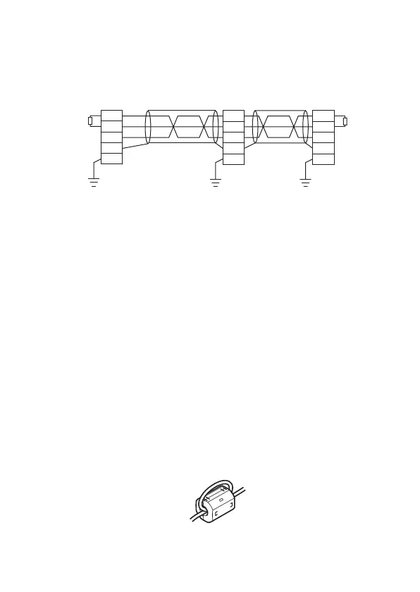
(c) The CC-Link module, the CC-Link stations and the FG line
inside the control panel should be connected at the FG
terminal as shown in the diagram below.
(d) Each power line connecting to the external power supply
terminal or module power supply terminal must be 30m (98.43
ft) or less.
(e) Install a noise filter to the external power supply. Use a noise
filter with an attenuation characteristic equivalent to that of the
MA1206 (TDK-Lambda Corporation). Note that a noise filter is
not required when the module is used in Zone A defined in
EN61131-2.
(f) Keep the length of signal cables connected to the analog input
terminals of the following modules to 30m or less.
Wire cables connected to the external power supply and
module power supply terminal in the control panel where the
module is installed.
• AJ65BT-64RD3
• AJ65BT-64RD4
• AJ65BT-68TD
(g) For the cable connected to the power supply terminal of the
AJ65SBT-RPS, AJ65SBT-RPG or AJ65BT-68TD, attach a
ferrite core with an attenuation characteristic equivalent to that
of the ZCAT3035- 1330 from TDK Corporation. Twist the cable
around the ferrite core by one as shown below.
(Yellow)
(White)
(Blue)
FG
SLD
DG
DB
DA
FG
SLD
DG
DB
DA
FG
SLD
DG
DB
DA
cable
dedicated
CC-Link
cable
dedicated
CC-Link
resistor
Terminal
Local module
Remote module
Master module
resistor
Terminal
[Simplified diagram]

 Loading...


