43
(h) Do not bind 100VAC and 24VDC wires together with main
circuit (high tension and large current) wires or I/O signal lines
(including common line) nor place them near each other.
Provide 100mm (3.94 inch) clearance between the wires if
possible.
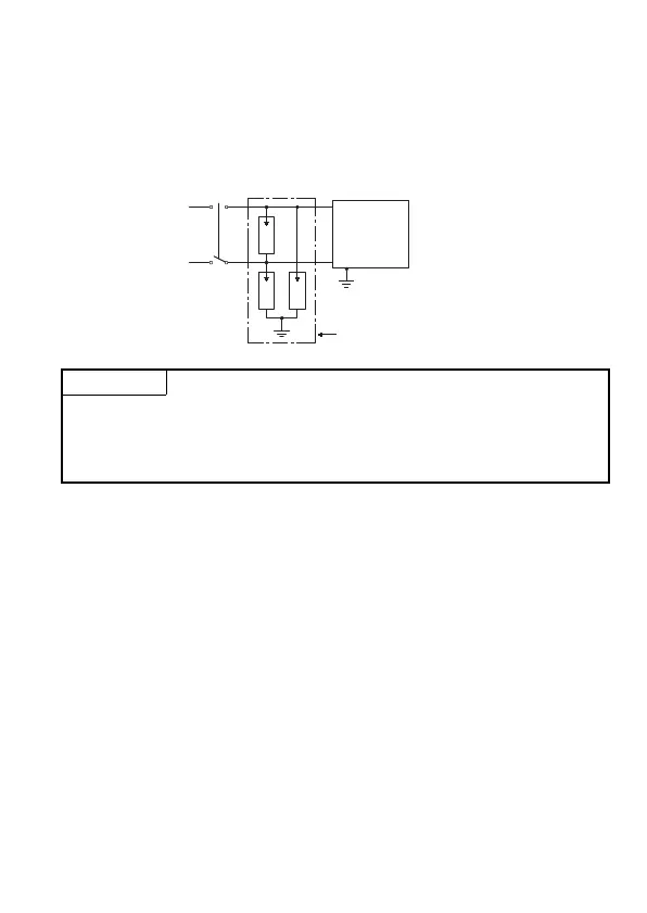
(i) As a countermeasure to power surge due to lightening,
connect a surge absorber for lightening as shown below.
(2) Wiring to I/O device
(a) The solderless terminal with insulation sleeve is inapplicable to
a terminal block.
It is advisable to cover the wire connection part of a terminal
with a mark tube or insulation tube.
(b) Install wiring to a terminal block using the cable of core
diameter 0.3 to 0.75mm
2
, and outside diameter 2.8mm or less.
(c) Run the I/O line and output line away from each other.
POINT
(1) Separate the ground of the surge absorber for lightening (E1) from that of the
programmable controller (E2).
(2) Select a surge absorber for lightening whose power supply voltage does no exceed the
maximum allowable circuit voltage even at the time of maximum power supply voltage
elevation.
E1E1
devicesI/O
controller
Programmable
Surge absorber for lightening
E2
E1
AC

 Loading...


