55
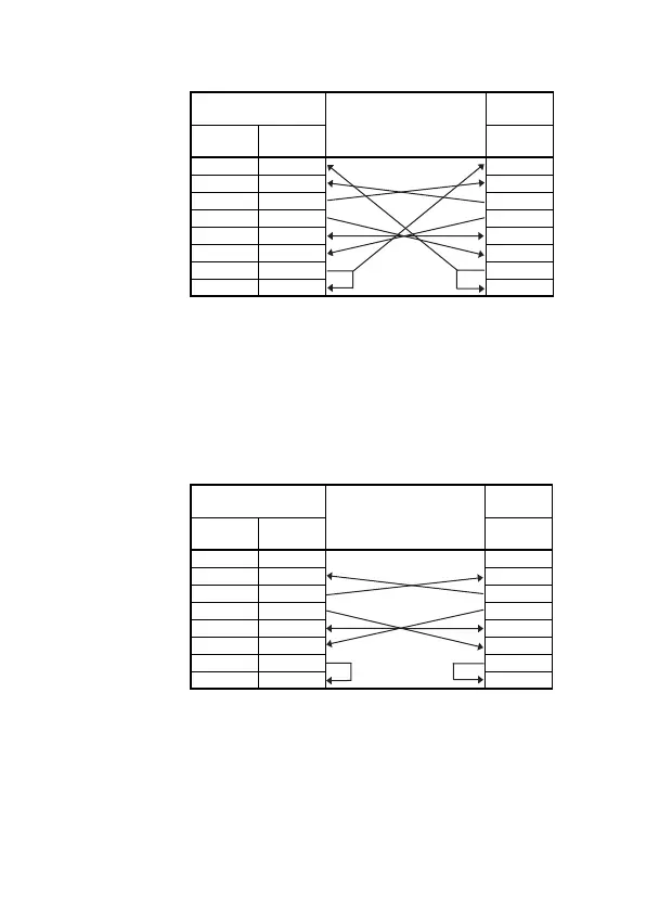
(a) Example connection to an external device in which the CD
signal (pin No.8) can be switched ON and OFF.
(b) Example connection to an external device in which the CD
signal (pin No.8) cannot be switched ON and OFF.
In the case of a connection to a device in which the device's
CD signal cannot be switched ON and OFF, set non-execution
of the buffer memory address 10BH RS232C CD terminal
check.
1) Example connection to an external device in which DC
code control or DTR/DSR code control is executed.
A1SCPUC24-R2
Cable
Connections and
Signal Directions
External
Device
Signal
Names
Pin
Number
Signal
Names
CD 1 CD
RD(RXD) 2 RD(RXD)
SD(TXD) 3 SD(TXD)
DTR(ER) 4 DTR(ER)
SG 5 SG
DSR(DR) 6 DSR(DR)
RS(RTS) 7 RS(RTS)
CS(CTS) 8 CS(CTS)
A1SCPUC24-R2
Cable
Connections and
Signal Directions
External
Device
Signal
Names
Pin
Number
Signal
Names
CD 1 CD
RD(RXD) 2 RD(RXD)
SD(TXD) 3 SD(TXD)
DTR(ER) 4 DTR(ER)
SG 5 SG
DSR(DR) 6 DSR(DR)
RS(RTS) 7 RS(RTS)
CS(CTS) 8 CS(CTS)
 Loading...


