APP - 28
APPENDICES
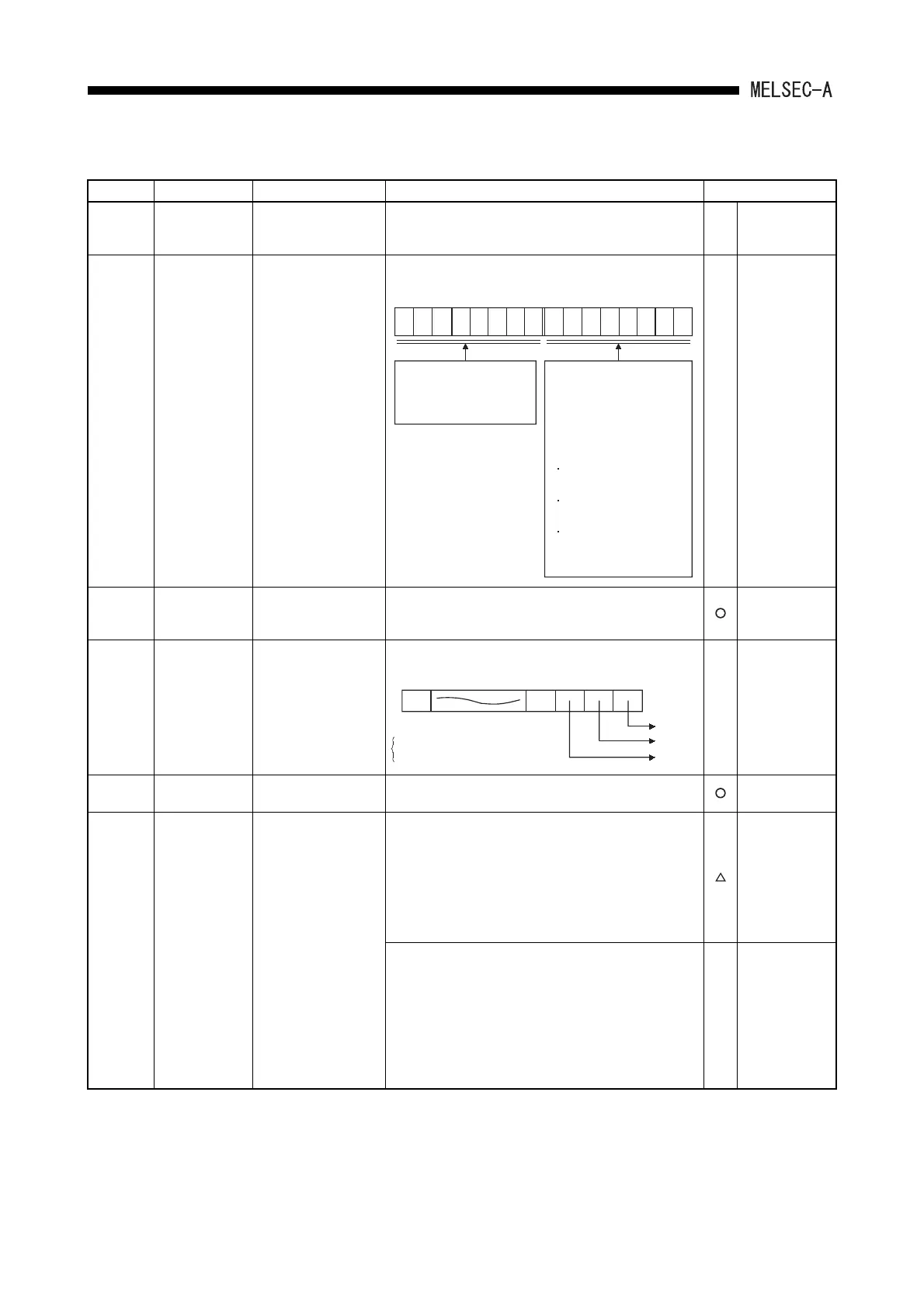
Table App2.2 Special Register List (Continue)
Number Name Description Details Applicable CPU
D9003
SUM instruction
detection bits
The number of bits
detected by SUM
instruction detection.
• The number of bits detected by execution of the SUM
instruction are stored. in BIN code and updated every
execution thereafter.
—
Dedicated to
A0J2H.
*1
D9004
MINI link master
module error
Error detection status
• Error status of the MINI (S3) link detected on loaded
MINI (S3) link module is stored.
—
Usable with
AnA, A2AS,
AnA board and
AnU.
*1
D9005
AC DOWN
counter
AC DOWN count
• 1 is added each time input voltage becomes 85% or
less of rating while the CPU unit is performing
operation, and the value is stored in BIN code.
Usable with all
types of CPUs.
D9006 Battery low
Indicates the CPU
module of which
battery voltage is low.
• Bits which correspond to CPU of which battery is low
are turned on in D9006, as shown below.
—
Dedicated to
A3V.
*1
D9008
Shelf-diagnostic
error
Self-diagnostic error
number
• When error is found as a result of self-diagnosis, error
number is stored in BIN code.
Usable with all
types of CPUs.
D9009
Annunciator
detection
F number at which
external failure has
occurred
• When one of F0 to 255 is turned on by OUT F or
SET F , the F number, which has been detected
earliest among the F numbers which have turned on, is
stored in BIN code.
• D9009 can be cleared by RST F or LEDR
instruction. If another F number has been detected, the
clearing of D9009 causes the next number to be stored
in D9009.
Unusable with
A3, A3N, A3A,
A73 and A3N
board.
• When one of F0 to 255 is turned on by OUT F or
SET F , the F number, which has been detected
earliest among the F numbers which have turned on, is
stored in BIN code.
• D9009 can be cleared by executing RST F or LEDR
instruction or moving INDICATOR RESET switch on
CPU front to ON position. If another F number has
been detected, the clearing of D9009 causes the nest
number to be stored in D9009.
—
Usable with A3,
A3N, A3A, A73
and A3N board.
b15 b8 b7 b0
Bits which correspond
to the signals of MINI
(S3) link module,
shown below, are
turned on as the signals
are turned on.
Hardware error
(X0/X20)
MINI(S3) link error
detection (X6/X26)
MINI(S3) link
communication error
(X7/X27)
to to
87654321 87654321
Data communication
between the PLC CPU
and MINI (S3) link
module is disabled.
0 0
B3 B0B1B2
CPU B
CPU C
CPU A
0: Normal
1: Battery low
B15
 Loading...


