2 - 28
SYSTEM CONFIGURATION2.
(a) A2USHCPU-S1, A2USCPU-S1, A2ACPU-S1 and A2ASCPU-S30 system
System configuration
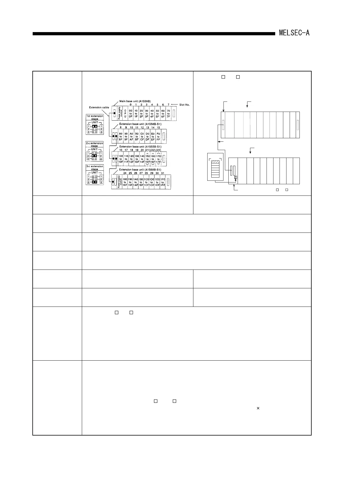
[When the AnS dedicated extension base is used]
An example when the 64-point module is installed to
each slot is shown.
[When the A N, A A extension base is used]
An example when the 64-point module is installed to
each slot is shown.
Maximum number of
extension stages
3rd extension stage 1st extension stage
Maximum number of
I/O modules
16 modules
Maximum number of
I/O points
1024 points
Main base unit model
name
A1S32B, A1S33B, A1S35B, A1S38B
Extension base unit
model name
A1S65B(S1), A1S68B(S1), A1S52B(S1),
A1S55B(S1), A1S58B(S1)
A62B, A65B, A68B, A52B, A55B, A58B
Extension cable
model name
A1SC03B, A1SC07B, A1SC12B, A1SC30B,
A1SC01B (right-side installation), A1SC60B
A1SC05NB, A1SC07NB, A1SC30NB, A1SC50NB
Notes
(1) Only one A N, A A extension base can be used. (The second extension module cannot be used.)
(2) When the extension base A1S52B(S1), A1S55B(S1), A58B(S1) or A52B, A55B, A58B are used, the 5VDC
power is supplied from the power supply module of the main base unit. Before use, refer to Section 6.1.3
and examine if it can be used.
(3) Limit the length of extension cable to 6m (236inch) or shorter.
(4) When using the extension cable, do not tie it with the main circuit cables, which has high voltage, large
current, or install them close to each other.
I/O number
assignment
(When I/O assignment is
not performed)
(1) Assign I/O numbers to the main base unit first, then to the extension base unit.
(2) Assign I/O numbers as if both main base unit and extension base unit have 8 slots each. When the
A1S32B/A1S33B/A1S35B for 2/3/5 slots are used as the main base unit, add 6/5/3 slots (96 points/80
points/48 points) and assign the extension base unit I/O numbers.
(3) 16 points are assigned to an empty slot.
(4) When an extension base for A N or A A is used, be sure to set to a single extension level. If it is set to
the number of skipped stages, 16 points/slot are assigned to all of skipped stages 8 slots, and thus it does
not work.
(5) Items (2) to (3) can be changed by the I/O assignment.
(Refer to the ACPU/QCPU-A (A Mode) Programming Manual (Fundamentals).)
0234
5
617
8 9 10 11 12 13
14 15
200 240
27F
280
2BF
2C0
2FF
300
33F
340
37F
380
3BF
3C0
3FF
23F
00
3F
40
7F
80
BF
C0
FF
100
13F
140
17F
180
1BF
1C0
1FF
UNIT
1
2
3
4
5
6
7
1
2
3
4
5
6
7
Main base
unit
(A1S38B)
Slot No.
Slot No.
Extension cable
1st extension
stage
Power supply
module
Power supply
module
CPU module
to
toto
to to to to to to to to
to to to to to
Extension base unit (for A N, A A)
 Loading...


