6
4-8 PIPING INSTALLATION
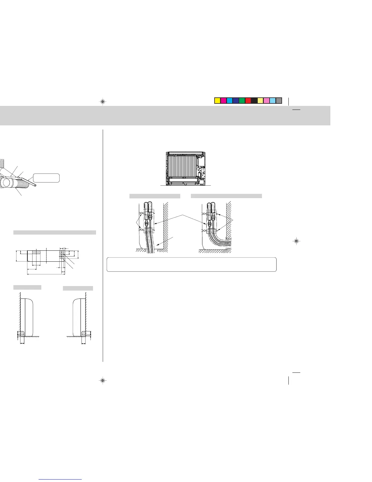
CONNECTING PIPE INSTALLATION
• Install the connecting pipes so that the piping can move slightly to the front, back, left, and right.
FOR RIGHT DOWNWARD PIPING
• Be sure to insulate the connecting pipes and place them near the rear of the indoor unit so that they do not
contact the front panel.
• Be careful not to crush the connecting pipes when bending them.
FOR PIPING OTHER THAN RIGHT DOWNWARD
Bands 5
Bands 5
Remove the cover.
Pipe covers 4
FOR RIGHT DOWNWARD OR LEFT DOWNWARD PIPING
(The following figure is a view of the bottom of the indoor
unit from above.)
FOR REAR OR LEFT-REAR PIPING
(The following figure is a front view of the indoor
unit installation location.)
FOR LEFT PIPING
FOR RIGHT PIPING
When the unit is
installed on the wall.
When the unit is
installed on the floor.
DETERMINING HOLE POSITIONS
• The areas where the piping can be routed are indicated with oblique lines in the figure.
4-7 MAKING HOLES IN THE WALL AND FLOOR
MAKING HOLES
1 Make ø65 mm holes (ø75 mm for KA50) that are approximately 5–7 mm deep and angled slightly downward
outward from the room.
2 Insert the wall hole sleeves C into the holes.
Wall hole
(Indoor side)
(Wall hole cross section)
Wall thickness
One scale
Wall hole sleeve C
Cut with 1 extra
scale length.
65 mm dia.
(ø75 mm for KA50)
Caution:
Be sure to use the wall hole sleeves C. Otherwise, the indoor/outdoor unit connecting wires may
contact a metal object in the wall or, in the case of hollow walls, small rodents may gnaw on the wires,
resulting in a very dangerous situation.
 Loading...