17. FULLY CLOSED LOOP SYSTEM
17 - 13
(5) Setting of feedback pulse electronic gear
POINT
If an incorrect value is set in the feedback pulse electronic gear ([Pr. PE04], [Pr.
PE05], [Pr. PE34], and [Pr. PE35]), [AL. 37 Parameter error] and an abnormal
operation may occur. Also, it may cause [AL. 42.8 Fully closed loop control error
by position deviation] during the positioning operation.
The numerator ([Pr. PE04] and [Pr. PE34]) and denominator ([Pr. PE05] and [Pr. PE35]) of the electronic
gear are set to the servo motor-side encoder pulse. Set the electronic gear so that the number of servo
motor encoder pulses per servo motor revolution is converted to the number of load-side encoder
pulses. The relational expression is shown below.
[Pr. PE04] × [Pr. PE34]
[Pr. PE05] × [Pr. PE35]
Number of motor encoder pulses per servo motor revolution
Number of load side encoder pulses per servo motor revolution
=
Select the load-side encoder so that the number of load-side encoder pulses per servo motor revolution
is within the following range.
4096(2
12
) ≤ Number of load-side encoder pulses per servo motor revolution ≤ 67108864 (2
26
)
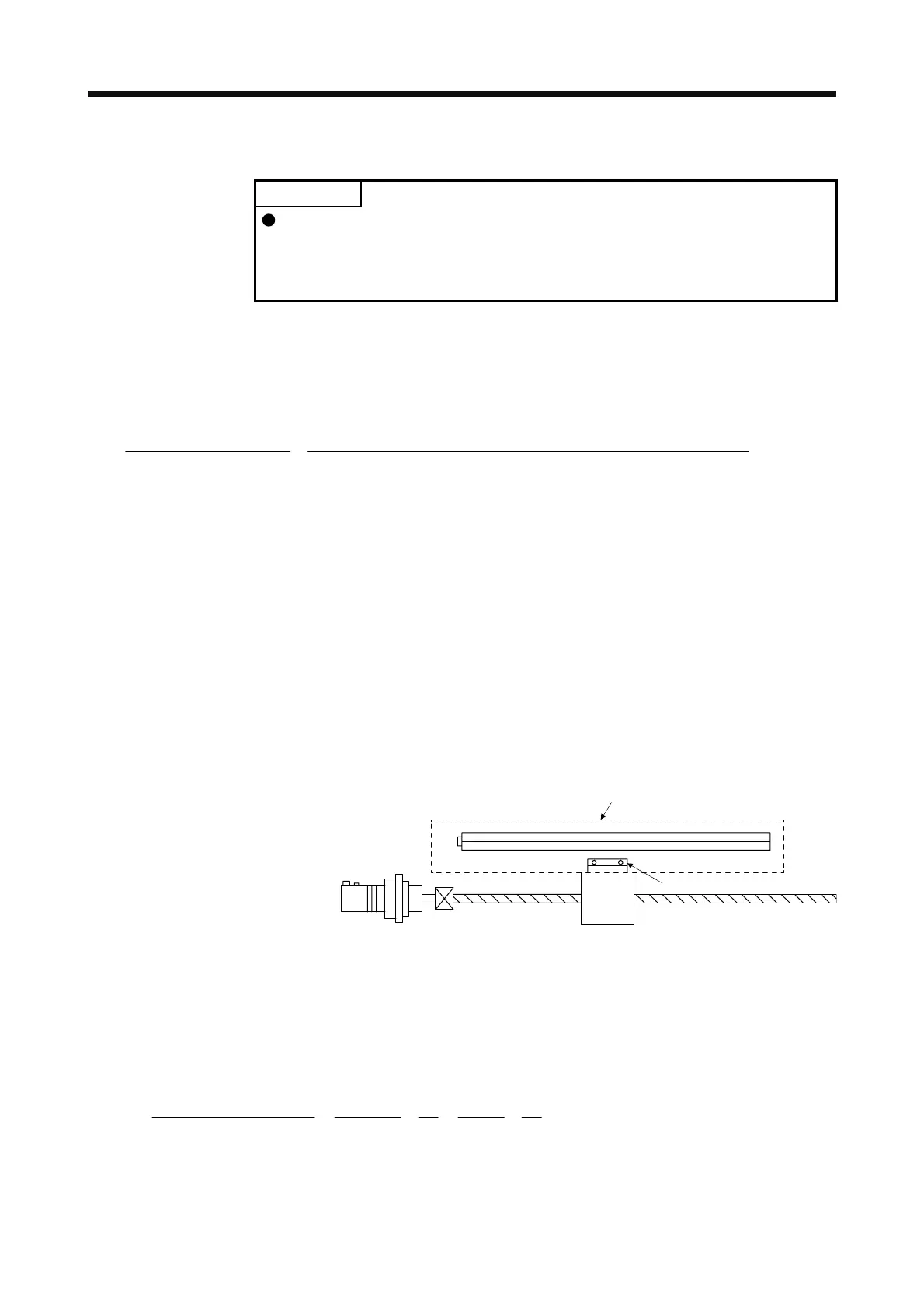
(a) When the servo motor is directly coupled with a ball screw and the linear encoder resolution is 0.05
μm
Conditions
Servo motor resolution: 4194304 pulses/rev
Servo motor reduction ratio: 1/11
Ball screw lead: 20 mm
Linear encoder resolution: 0.05 µm
Geared servo motor
Table
Linear encode
Linear encoder head
Calculate the number of linear encoder pulses per ball screw revolution.
Number of linear encoder pulses per ball screw revolution
= Ball screw lead/linear encoder resolution
= 20 mm/0.05 µm = 400000 pulses
[Pr. PE04] × [Pr. PE34]
[Pr. PE05] × [Pr. PE35]
400000
4194304
3125
32768
1
11
=
1
11
=××
 Loading...

