3. SIGNALS AND WIRING
3 - 20
3.3 Explanation of power supply system
3.3.1 Signal explanations
POINT
For the layout of connector and terminal block, refer to chapter 9 DIMENSIONS.
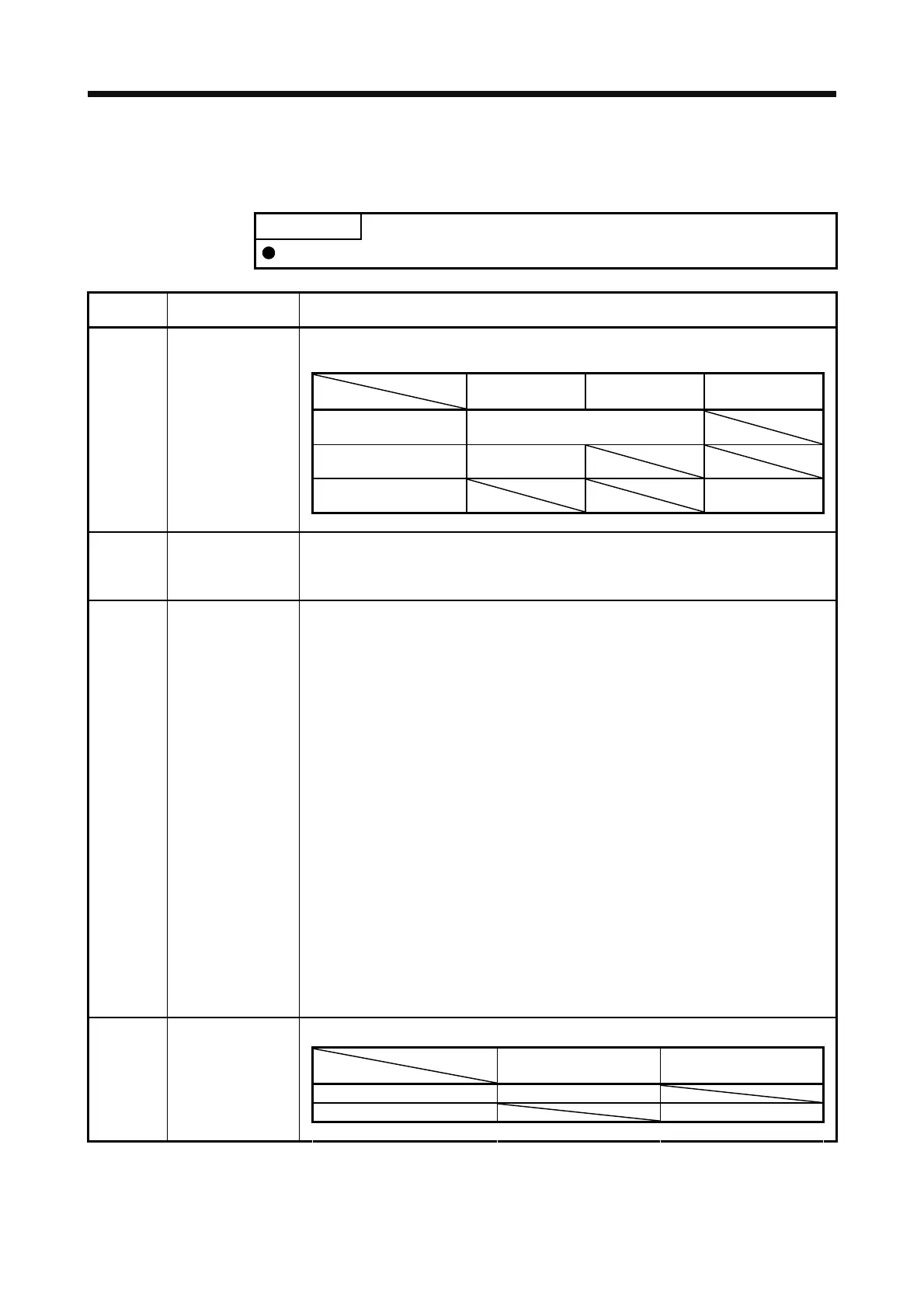
Symbol
Connection target
(application)
Description
Supply the following power to L1, L2, and L3. For 1-phase 200 V AC to 240 V AC, connect the
power supply to L1 and L3. Leave L2 open.
Servo amplifier
Power
MR-J4-10A(-RJ) to
MR-J4-70A(-RJ)
MR-J4-100A(-RJ) to
MR-J4-22KA(-RJ)
MR-J4-60A4(-RJ) to
MR-J4-22KA4(-RJ)
3-phase 200 V AC to 240
V AC, 50 Hz/60 Hz
L1/L2/L3
1-phase 200 V AC to 240
V AC, 50 Hz/60 Hz
L1/L3
3-phase 380 V AC to 480
V AC, 50 Hz/60 Hz
L1/L2/L3
L1/L2/L3
Main circuit power
supply
P3/P4
Power factor
improving
DC reactor
When not using the power factor improving DC reactor, connect P3 and P4(factory-wired).
When using the power factor improving DC reactor, disconnect P3 and P4, and connect the
power factor improving DC reactor to P3 and P4.
Refer to section 11.11 for details.
P+/C/D Regenerative option
(1) 200 V class
1) MR-J4-500A(-RJ) or less
When using a servo amplifier built-in regenerative resistor, connect P+ and D (factory-
wired).
When using a regenerative option, disconnect P+ and D, and connect the regenerative
option to P+ and C.
2) MR-J4-700A(-RJ) to MR-J4-22KA(-RJ)
MR-J4-700A(-RJ) to MR-J4-22KA(-RJ) do not have D.
When using a servo amplifier built-in regenerative resistor, connect P+ and C (factory-
wired).
When using a regenerative option, disconnect wires of P+ and C for the built-in
regenerative resistor. And then connect wires of the regenerative option to P+ and C.
(2) 400 V class
1) MR-J4-350A4(-RJ) or less
When using a servo amplifier built-in regenerative resistor, connect P+ and D. (factory-
wired)
When using a regenerative option, disconnect P+ and D, and connect the regenerative
option to P+ and C.
2) MR-J4-500A4(-RJ) to MR-J4-22KA4(-RJ)
MR-J4-500A4(-RJ) to MR-J4-22KA4(-RJ) do not have D.
When using a servo amplifier built-in regenerative resistor, connect P+ and C. (factory-
wired)
When using a regenerative option, disconnect wires of P+ and C for the built-in
regenerative resistor. And then connect wires of the regenerative option to P+ and C.
Refer to section 11.2 to 11.5 for details.
Supply the following power to L11 and L21.
Servo amplifier
Power
MR-J4-10A(-RJ) to
MR-J4-22KA(-RJ)
MR-J4-60A4(-RJ) to
MR-J4-22KA4(-RJ)
1-phase 200 V AC to 240 V AC L11/L21
1-phase 380 V AC to 480 V AC L11/L21
L11/L21
Control circuit power
supply
 Loading...

