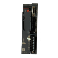
Do you have a question about the Mitsubishi MR-JE-70B and is the answer not in the manual?
| Model | MR-JE-70B |
|---|---|
| Series | MR-JE |
| Type | Servo Amplifier |
| Rated Output Power | 0.7 kW |
| Cooling Method | Natural Air Cooling |
| Feedback System | Incremental Encoder |
| Supply Voltage | AC 200V |
| Communication | SSCNET |
| Protection Features | Overcurrent, Overvoltage, Overload, Overheat, Encoder Error |
Details technical specifications like output, power supply, interface, and environmental conditions.
Specifies correct installation orientation and required space for optimal performance and safety.
Explains essential wiring for power supply connection, including contactors and protection.
Provides diagrams for connecting digital I/O signals using sink and source interfaces.
Illustrates timing sequences for alarm occurrences and their impact on servo motor operation.
Explains proper grounding procedures for servo amplifier and motor to prevent noise and shocks.
Step-by-step guide for initial power-up, including checks and parameter settings.
Guidance on performing test operations with servo motor and machine connected.
Details on using test operation modes like JOG, positioning, and program operations.
Using software for JOG, positioning, and other test operations without a controller.
An overview of all available parameters, categorized for easy reference and selection.
Details parameters for fundamental configuration like regenerative option and auto tuning.
Lists parameters for adjusting servo gains and filter settings for performance tuning.
Explains automated gain adjustment using MR Configurator2 for optimal system performance.
Details the real-time auto tuning function to automatically set optimum servo gains.
Explains various filters like machine resonance and low-pass filters for vibration suppression.
Comprehensive list of servo amplifier alarms, their causes, and recommended deactivation methods.
Details servo amplifier warnings, their descriptions, and stop methods.
Describes how the servo amplifier protects against motor and amplifier overloads.
Information on the software used for parameter setting, monitoring, and test operations.
Provides representative wiring diagrams conforming to international standards.
Recommendations for periodic inspections and replacement of parts with limited service life.


 Loading...