3. SIGNALS AND WIRING
3 - 19
3.5 Signal (device) explanations
For the I/O interfaces (symbols in I/O division column in the table), refer to section 3.8.2.
The pin numbers in the connector pin number column are those in the initial status.
3.5.1 Input device
(1) Input device pin
The following shows the input device pins and parameters for setting devices.
Connector pin No. Parameter Initial device I/O division
CN3-2 (Note) [Pr. PD03]
Not assigned
(always off)
CN3-12 (Note) [Pr. PD04]
Not assigned
(always off)
DI-1
CN3-19 (Note) [Pr. PD05]
Not assigned
(always off)
Note. When using external input signals (FLS, RLS, and DOG) of the servo amplifier with a
controller, assign devices to CN3-2, CN3-12, and CN3-19 pins. The CN3-2, CN3-12,
and CN3-19 pins are available with servo amplifiers having software version C5 or
later, and manufactured in May 2016 or later. For the servo amplifiers manufactured
in China, these pins have been available from the June 2016 production.
(2) Input device explanations
Device Symbol
Connector
pin
number
Function and application
I/O
division
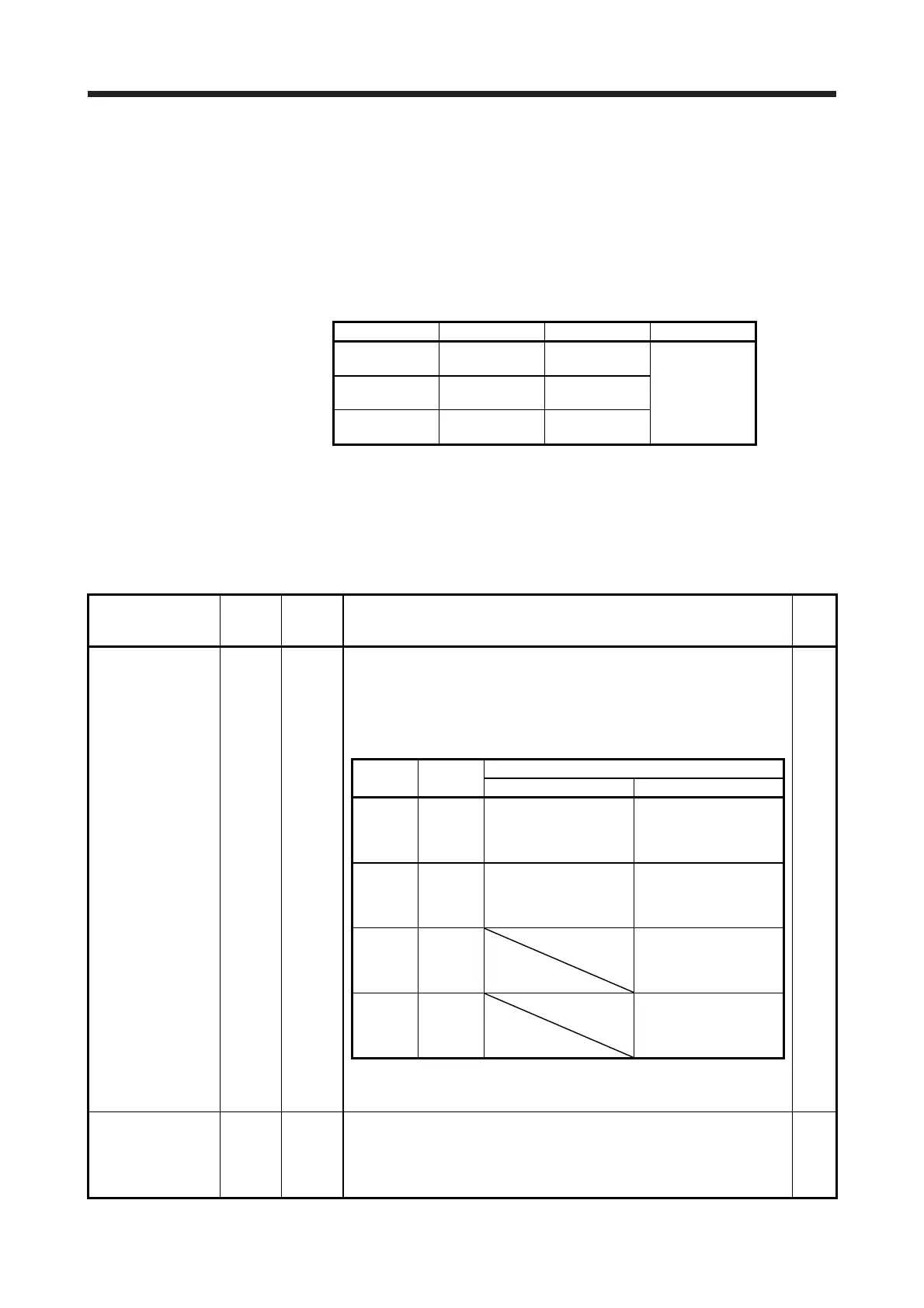
Forced stop 2 EM2 CN3-20
Turn off EM2 (open between commons) to decelerate the servo motor to a stop
with commands.
Turn EM2 on (short between commons) in the forced stop state to reset that
state.
Set [Pr. PA04] to "2 1 _ _" to disable EM2.
The following shows the setting of [Pr. PA04].
DI-1
[Pr. PA04]
setting
EM2/EM1
Deceleration method
EM2 or EM1 is off Alarm occurred
0 0 _ _ EM1
MBR (Electromagnetic
brake interlock) turns off
without the forced stop
deceleration.
MBR (Electromagnetic
brake interlock) turns off
without the forced stop
deceleration.
2 0 _ _ EM2
MBR (Electromagnetic
brake interlock) turns off
after the forced stop
deceleration.
MBR (Electromagnetic
brake interlock) turns off
after the forced stop
deceleration.
0 1 _ _
Not using
EM2 and
EM1
MBR (Electromagnetic
brake interlock) turns off
without the forced stop
deceleration.
2 1 _ _
Not using
EM2 and
EM1
MBR (Electromagnetic
brake interlock) turns off
after the forced stop
deceleration.
EM2 and EM1 are mutually exclusive.
Note that EM2 has the same function as EM1 in the torque control mode.
Forced stop 1 EM1 (CN3-20)
When using EM1, set [Pr. PA04] to "0 0 _ _" to enable EM1.
When EM1 is turned off (open between commons), the base circuit shuts off,
and the dynamic brake operates to decelerate the servo motor to a stop.
The forced stop will be reset when EM1 is turned on (short between commons).
Set [Pr. PA04] to "0 1 _ _" to disable EM1.
DI-1
 Loading...

