4
Your company internal use only.Copyright (C) Mitsubishi Electric Corporation.
NR-261UM-07LAN4,-07-5WS
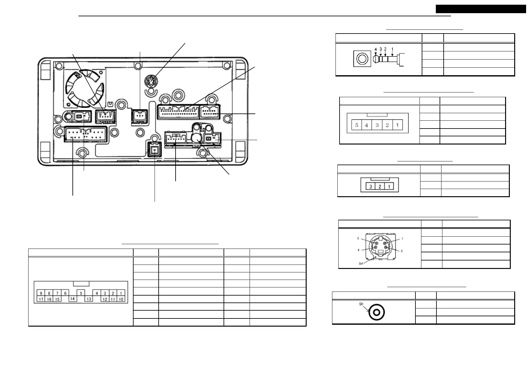
CONNECTORS
ANT001
Radio Antenna
Connector 1P
P708
Navi Power Supply
Connector 5P
P705
Rear Camera
Connector 12P
P707
RSES Connector 3P
P20C
Digital Sound Output Connector 4P
P703
VTR & Remote Control
Connector P32
P1G1
External Equipment
Connector 7P
P2A1
Audio Power Supply
Connector 17P
P2Z0
GPS Antenna Connector 2P
J1001 PinNo. Signal Name
1I2C-SDA
2GND
3I2C-SCL
4I2C-VCC
Version Up Key Terminal 4P
P708 PinNo. Signal Name
1GND
2PS-R
3 -
4 -
5BATTERY (+)
Navi Power Supply Connector 5P
*Connector figures are view where it faced the unit.
*Attention of pin numbering different from schematic diagram.
RSES Connector 3P
P707 PinNo. Signal Name
1 SHIELD (REAR)
2 REAR SIGNAL
3 -
P20C PinNo. Signal Name
1-
2-
3-
4-
SH SHIELD
Digital Sound Output Connector 4P
P2A1 PinNo. Signal Name PinNo. Signal Name
1 MAIN GND 10 BATTERY (+)
2 SPEAKER RR- 11 SPEAKER RR+
3 SPEAKER FR- 12 SPEAKER FR+
4 AMP DATA 13 ACCESSORY (+)
5 - 14VSS
6 SHIELD (AMP DATA) 15 SPEAKER FL+
7 SPEAKER FL- 16 SPEAKER RL+
8 SPEAKER RL- 17 ILL+
9 ILL CONTROL
Audio Power Supply Connector 17P
ANT001 PinNo. Signal Name
1 RAD IO AN TEN N A SIGNAL
SH SHIELD
Radio Antenna Connector 1P
P001
TMC Antenna Distribution
Output Connector 3P
P603
TMC Antenna
Connector 3P
 Loading...