Do you have a question about the Mitsubishi NR-261UM-07LAN4 and is the answer not in the manual?
| Brand | Mitsubishi |
|---|---|
| Model | NR-261UM-07LAN4 |
| Category | Car Navigation system |
| Language | English |
Details navigation features including HDD, GPS, route calculation, and voice guidance.
Covers audio playback, CD recording, amplifier, and EQ functions.
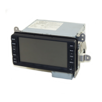
Describes the 6.95" TFT LCD, touch panel, and tactile switch features.
Lists various connectivity and auxiliary functions like VTR, RSES, remote control, and hands-free.
Provides technical details such as power supply, voltage, current consumption, dimensions, and weight.
Illustrates the front panel controls and layout when the panel is closed.
Shows the front panel controls and slots when the panel is open, including disc slot and eject.
Details the pinout and signals for the Version Up Key Terminal (J1001).
Lists the pinout and signals for the Navi Power Supply Connector (P708).
Details the pinout and signals for the RSES Connector (P707).
Lists the pinout and signals for the Digital Sound Output Connector (P20C).
Details the pinout and signals for the Audio Power Supply Connector (P2A1).
Lists the pinout and signals for the Radio Antenna Connector (ANT001).
Details the pinout and signals for the TMC Antenna Distribution Connector (P001).
Lists the pinout and signals for the TMC Antenna Connector (P603).
Details the pinout and signals for the VTR & Remote Control Connector (P703).
Lists the pinout and signals for the Rear Camera Connector (P705).
Details the pinout and signals for the External Equipment Connector (P1G1).
Lists the pinout and signals for the GPS Antenna Connector (P2Z0).
Diagram illustrating the overall system composition and component interconnections.
Details the system configuration when CAN communication is not supported, showing connected components.
Outlines the system configuration for the 10MY-NAS 2DIN Audio Navi unit.
Details the system configuration when CAN communication is supported, showing connected modules.
Explains IE-Bus support and additional connections for USB-BOX and JCI Hands-free modules.
Comprehensive list of parts from M001 to M088, including their part numbers and locations.
Detailed list of hardware components, including screws and their specifications.
Detailed listing of capacitors (C003 to C7T9) with their specifications.
Comprehensive list of diodes (D1321 to D7A8) with their part numbers and specifications.
Detailed listing of transistors (Q001 to Q7A9) with their part numbers and specifications.
Comprehensive list of integrated circuits (IC0F1 to IC757) with part numbers and specifications.
Detailed list of connectors (P001 to P719) including part numbers and specifications.
Comprehensive list of coils (L001 to L7T9) with part numbers and specifications.
Detailed listing of individual resistors (R001 to R7T9) with their part numbers and specifications.
Detailed listing of crystals (X201 to X701) with their part numbers and specifications.
Detailed schematics for digital processing, memory, interfaces, and connectors.
Schematics for analog signal processing, power management, and vehicle interfaces.
Component layout diagrams for various printed circuit boards within the system.
