12
Your company internal use only.Copyright (C) Mitsubishi Electric Corporation.
NR-261UM-07LAN4,-07-5WS
DISASSEMBLING PROCEDURES
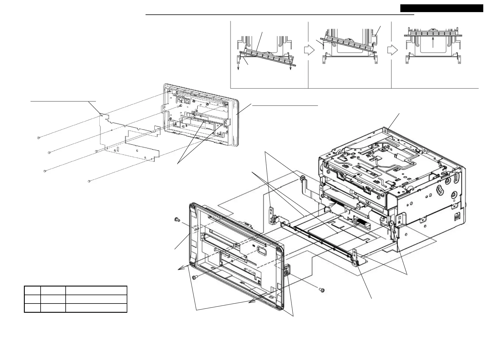
● Disassembling procedures
In reverse of assembling procedures.
● Assembling procedures
1.Hook M076 to M070, and screw the five screws(Ⓙ).
2.Pull out the slide part of the S3-CHASSIS, and pass the arm through
to the hole of the S3-PANEL-SUB.<Step1~3>
3.Screw the three screws(Ⓐ).
Ⓐ x 3
Ⓙ x 5
M076: ASSY-PCB-PANEL
M070: ASSY-PANEL-SUB
M3X6 0.7 +0.2/-0.1Ⓐ
0.12 +0.01/-0.012X4Ⓙ
Tighten torque(N・m)ScrewNo.
S3-CHASSIS
S3-PANEL-SUB
Remove the arm protector.
Remove the arm protector.
(1)After pull out the slide chassis till it stops, pass the
tip through to panel each one side. <Step1>
<Step1> Pass the tip of slide chassis
through to panel by each.
Slide chassis
S3-PANEL-SUB
Arm
Arm
<Step2> After passed the arm of one
side, pass the another side of arms.
<Step3> Push the front of panel.
(2)After passed the one arm, pass another
arm with bending it internally. <Step2>
Do not give scratch to panel by arms.
(3)Push the front of panel to
connector mating. <Step3>
(4) Push the square holes at side(two places) and
downside(three places), till the hooks set.<Step3>
Latch M076 to the hooks.
 Loading...