11
11
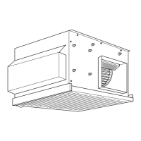
1-8.2. Connecting procedures
• The remote controller cord may be extended up to 500 m. Since the remote
controller cord supplied with the unit is 10 m-long, use those electric wires or
(two-core) cables of 0.3 mm
2
to 1.25 mm
2
for extension. Do not use multi-
conductor cables to prevent possible malfunction of the unit.
(1) Connect the remote controller cord to the terminal block for the lower
case.
Caution:
Do not use crimp-style terminals for connection to the remote controller ter-
minal block to eliminate contact with the boards and resultant trouble.
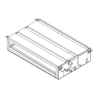
(2) Set the dip switch No.1 shown below when using two remote controller’s
for the same group.
Setting the dip switches
The dip switches are at the bottom of the remote controller. Remote controller
Main/Sub and other function settings are performed using these switches. Ordi-
narily, only change the Main/Sub setting of SW1. (The factory settings are all “ON”.)
<SW No. 1>
SW contents Main Remote controller Main/Sub setting
ON/OFF Main/Sub
Comment Set one of the two remote controllers at one group to “Main”
<SW No. 2>
SW contents Main When remote controller power turned on
ON/OFF Normally on/Timer mode on
Comment
When you want to return to the timer mode when the power
is restored after a power failure when a Program timer is
connected, select “Timer mode”.
<SW No. 3>
SW contents Main Cooling/heating display in AUTO mode
ON/OFF Yes/No
Comment
When you do not want to display “Cooling” and “Heating”
in the Auto mode, set to “No”.
<SW No. 4>
SW contents Main Intake temperature display
ON/OFF Yes/No
Comment
When you do not want to display the intake temperature,
set to “No”.
11
11
1-8.3. Fitting the upper case
(1) Put the upper latches (at two locations) first then fit the upper case into
the lower case as illustrated.
(2) To remove the upper case, put a slotted screwdriver tip in the latches as
shown in the diagram then move the screwdriver in the direction of ar-
row.
Caution:
• Do not move the screwdriver while inserting the tip far into the latches to
prevent broken latches.
• Be sure to put the screwdriver tip securely in the latches until a snap
sounds. Loosely inserted screwdriver may fall down.
Note:
The operating section is covered with a protective sheet. Before using the
unit, remember to remove the protective sheet.
11
11
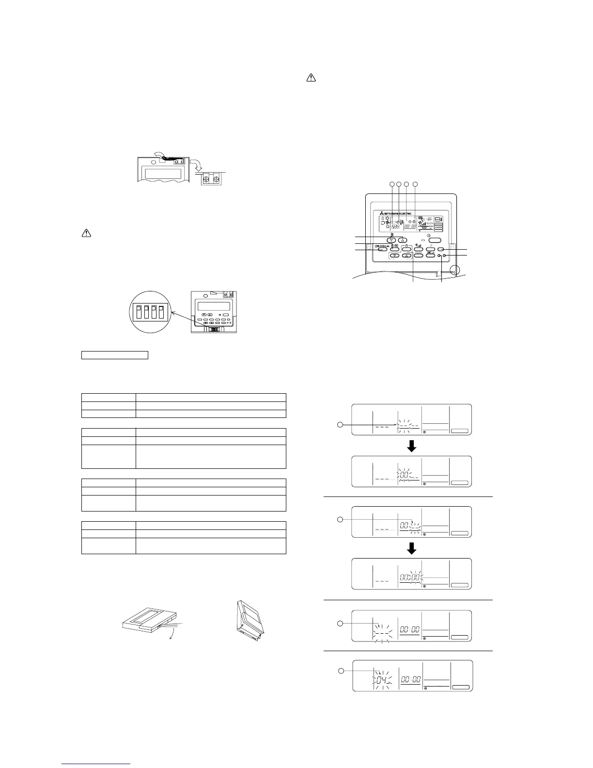
1-8.4. Function settings
(1) Wired type
Changing the power voltage setting
Be sure to change the power voltage setting when operating the unit in an area
where the power source is 220 V or 230 V.
(The power voltage setting is set to 240 V at the factory. Units that are used in
areas where the power source is 240 V do not require power voltage setting
changes.)
[Operating instructions] (entering settings with a wired remote controller)
 Loading...