EasyManua.ls Logo

Mitsubishi PLH-3AAK User Manual

Mitsubishi PLH-3AAK
86 pages
To Next Page IconTo Next Page
Page #1 background imageLoading...
Page #1 background image
TECHNICAL & SERVICE MANUAL
SPLIT-TYPE, HEAT PUMP AIR CONDITIONERS
No. OC360
NOTE:
• This manual does not
cover outdoor units.
When servicing outdoor
units, please refer to the
outdoor unit`s service
manual together with this
manual.
CONTENTS
1. REFERENCE MANUAL ······································2
2. PART NAMES AND FUNCTIONS ···················3
3. SPECIFICATIONS············································6
4. DATA ······························································14
5. OUTLINES AND DIMENSIONS ·····················28
6. WIRING DIAGRAM ········································31
7. REFRIGERANT SYSTEM DIAGRAM············32
8. TROUBLESHOOTING ···································34
9. FUNCTION SETTING·····································50
10. 4-WAY AIR FLOW SYSTEM ··························57
11. SYSTEM CONTROL ······································62
12. DISASSEMBLY PROCEDURE ······················76
13. PARTS LIST ···················································79
14. OPTIONAL PARTS ········································84
Indoor unit
[Model names] [Service Ref.]
PLH-3AAK
PLH-3AAK
PLH-4AAK
PLH-4AAK
PLH-5AAK
PLH-5AAK
PLH-6AAK
PLH-6AAK
PLH-3AAKH
PLH-3AAKH
PLH-4AAKH
PLH-4AAKH
PLH-5AAKH
PLH-5AAKH
PLH-6AAKH
PLH-6AAKH
February 2006
INDOOR UNIT
WIRED REMOTE
CONTROLLER
WIRELESS REMOTE
CONTROLLER
ON/OFF TEMP
ON/OFF
TEMP.
Model name
indication
OC360--1.qxp 06.2.24 1:56 PM Page 1

Table of Contents

Question and Answer IconNeed help?

Do you have a question about the Mitsubishi PLH-3AAK and is the answer not in the manual?

Mitsubishi PLH-3AAK Specifications

General IconGeneral
BrandMitsubishi
ModelPLH-3AAK
CategoryAir Conditioner
LanguageEnglish

Summary

PART NAMES AND FUNCTIONS

Indoor Unit Components

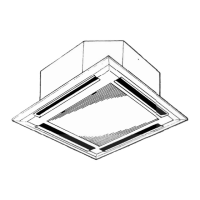
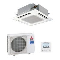
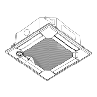
Identifies and describes the parts of the indoor unit.

Wired Remote Controller Overview

Details the layout and buttons of the wired remote controller.

Wireless Remote Controller Operation

Buttons, Displays, and Modes

Describes the functions of buttons, displays, and operation modes.

SPECIFICATIONS

Unit Specifications by Model

Provides detailed technical specifications for the unit models.

DATA

Cooling Capacity Performance Data (50Hz)

Presents cooling capacity performance data under various conditions.

Heating Capacity Performance and Correction Factors

Details heating capacity performance and correction factors.

ELECTRICAL DATA

Electrical Specifications by Voltage/Phase

Lists electrical data for different power supply configurations.

STANDARD OPERATION DATA

OUTLINES AND DIMENSIONS

WIRING DIAGRAM

Wiring Diagram, Legend, and Notes

Illustrates electrical connections, provides a legend, and notes.

Self-Diagnosis and Emergency Operation Procedures

Details error codes, symptoms, and emergency operation procedures.

REFRIGERANT SYSTEM DIAGRAM

Refrigerant Flow Diagrams by Model

Illustrates refrigerant flow for different system configurations.

TROUBLESHOOTING

Error Code Interpretation and Diagnosis Methods

Explains how to interpret error codes and diagnose malfunctions.

SELF-DIAGNOSIS ACTION TABLE

Error Code Diagnosis and Countermeasures

Provides a table linking error codes to causes and corrective actions.

TEST RUN AND EMERGENCY OPERATION

Test Run Procedures and Operation Checks

Describes how to perform test runs using wired and wireless controllers.

HOW TO CHECK THE PARTS

TEST POINT DIAGRAM

FUNCTIONS OF DIP SWITCH AND JUMPER WIRE

OUTDOOR UNIT SERVICE FUNCTIONS

Outdoor Controller Board Operational Functions

Details functions like compulsory defrosting and fan control.

FUNCTION SETTING

SYSTEM CONTROL

ONE REMOTE CONTROLLER (STANDARD) OPERATION

TWO-REMOTE CONTROLLER OPERATION

GROUP CONTROL OPERATION

POWER OUTAGE AUTOMATIC RECOVERY OPERATION

COMBINED REMOTE/HAND-HELD CONTROL

Related product manuals