EasyManua.ls Logo

Mitsubishi PLFY-P12NBMU-E User Manual

Mitsubishi PLFY-P12NBMU-E
36 pages
To Next Page IconTo Next Page
Page #1 background imageLoading...
Page #1 background image
TECHNICAL & SERVICE MANUAL
Indoor unit
[Model names] [Service Ref.]
PLFY-P12NBMU-E
PLFY-P15NBMU-E
PLFY-P18NBMU-E
PLFY-P24NBMU-E
PLFY-P30NBMU-E
PLFY-P36NBMU-E
No. OCH421
REVISED EDITION-B
CONTENTS
1. TECHNICAL CHANGES
.........................
2
2. FEATURES
.............................................
3
3. PART NAMES AND FUNCTIONS
..........
4
4. SPECIFICATIONS
...................................
6
5. 4-WAY AIR FLOW SYSTEM
.................
10
6. OUTLINES AND DIMENSIONS
............
13
7. WIRING DIAGRAM
...............................
14
8.
REFRIGERANT SYSTEM DIAGRAM
......
16
9. MICROPROCESSOR CONTROL
.........
17
10. TROUBLESHOOTING
.........................
24
11. DISASSEMBLY PROCEDURE
.............
33
SPLIT-TYPE, HEAT PUMP AIR CONDITIONERS
PLFY-P12NBMU-E PLFY-P12NBMU-ER1
PLFY-P12NBMU-ER2
PLFY-P15NBMU-E PLFY-P15NBMU-ER1
PLFY-P15NBMU-ER2
PLFY-P18NBMU-E PLFY-P18NBMU-ER1
PLFY-P18NBMU-ER2
PLFY-P24NBMU-E PLFY-P24NBMU-ER1
PLFY-P24NBMU-ER2
PLFY-P30NBMU-E PLFY-P30NBMU-ER1
PLFY-P30NBMU-ER2
PLFY-P36NBMU-E PLFY-P36NBMU-ER1
PLFY-P36NBMU-ER2
Note:
This manual does not
cover outdoor units.
When servicing them,
please refer to the outdoor
unit’s service manual.
• RoHS compliant products
have <G> mark on the
spec name plate.
April 2012
INDOOR UNIT
Model name
indication
PARTS CATALOG (OCB421)
R410A / R22
Revision:
PLFY-P12/15/18/24/30/36
NBMU-ER2 have been
added in REVISED
EDITION-B.
Some descriptions have
been modified.
Please void OCH421
REVISED EDNTION-A.
Question and Answer IconNeed help?

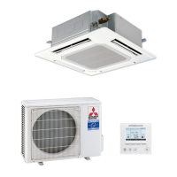
Do you have a question about the Mitsubishi PLFY-P12NBMU-E and is the answer not in the manual?

Mitsubishi PLFY-P12NBMU-E Specifications

General IconGeneral
BrandMitsubishi
ModelPLFY-P12NBMU-E
CategoryAir Conditioner
LanguageEnglish

Summary

FEATURES

PART NAMES AND FUNCTIONS

Indoor unit

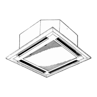
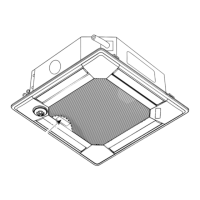
Details components and functions of the indoor unit.

Wired remote controller

Explains the operation and display sections of the wired remote controller.

SPECIFICATIONS

4-1. SPECIFICATIONS

Technical specifications for various models, including capacity, power, and dimensions.

WIRING DIAGRAM

Indoor Unit Wiring Diagram

Detailed wiring schematic for the indoor unit and its components.

MICROPROCESSOR CONTROL

9-1. COOL OPERATION

Details on thermostat, anti-freezing, and fan control during cooling operation.

9-4. HEAT OPERATION

Control modes for heat operation, including thermostat, fan, hot adjust, and defrosting.

TROUBLESHOOTING

10-1. HOW TO CHECK THE PARTS

Procedures for checking resistance and voltage of key components like thermistors and motors.

Thermistor Characteristics

Thermistor characteristic graph and resistance values at different temperatures.

Linear Expansion Valve Operation

Operation summary and connection diagram for the linear expansion valve.

Valve Operation Troubleshooting

Troubleshooting steps for linear expansion valve issues like locking or short circuits.

DC Fan Motor Troubleshooting

Procedures for checking DC fan motor wiring, power supply, and sensor signals.

FUNCTION OF DIP SWITCH

DIP Switch Functions

Explains the function of various DIP switches for unit settings and operation.

TEST POINT DIAGRAM

Indoor Controller Board Test Points

Test points diagram for the indoor controller board, showing component locations.

DISASSEMBLY PROCEDURE

Related product manuals