1.1. Before test run
The test run can be carried out either from the outdoor unit or the indoor unit.
1. Checklist
• After the installation, piping setup, and wiring of the indoor and outdoor units is
complete, check that refrigerant is not leaking, the power and control wires are
not loose, and the poles are not reversed.
• Use a 500 V insulation resistance tester to make sure that the resistance be-
tween the power terminal and the ground is 1.0 MΩ or more. If it is less than
1.0 MΩ, do not operate the unit. * Absolutely do not touch the tester to indoor/
outdoor connection terminals S1, S2, and S3. An accident could occur.
• Make sure there is no malfunction in the outdoor unit. (If there is a malfunction,
you can diagnose it using LED2 on the board.)
• Check that the ball valve is fully open on both the liquid and gas ends.
• Check the electrical power phase. If the phase is reversed, the fan may rotate
in the wrong direction or stop, or unusual sounds may be produced.
• Starting at least 12 hours before the test run, send current through the
crankcase heater. (If the current is running for a shorter period of time,
damage to the compressor could result.)
• For specific models requiring changing of settings for higher ceilings or selec-
tion of power supply ON/OFF capability, make proper changes referring to the
description for Selection of Functions through Remote Controller.
After the above checks are complete, carry out the test run as indicated in the
following outline.
1.2. Test run procedures
1) Indoor unit
Operating procedures
1 Turn on the main power supply
While the room temperature display on the remote controller reads “CENTRALLY
CONTROLLED”, the remote controller is disabled. Turn off the “CENTRALLY
CONTROLLED” display before using the remote controller.
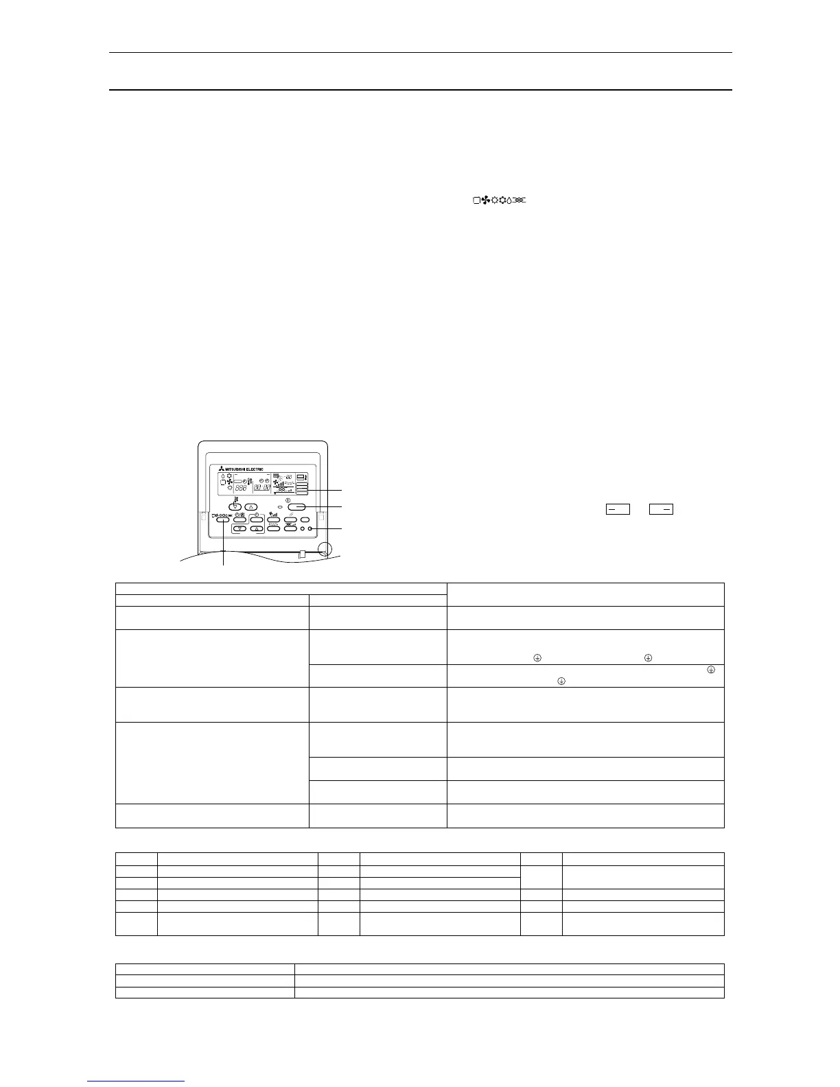
2 Press “TEST RUN” button twice
A The ‘TEST RUN’ indicator should light up.
3 Press button
Cooling/drying mode: Cool air should start to blow.
Heating mode: Warm air should start to blow (after a while).
4 Check the outdoor unit fan for correct running
The outdoor unit features automatic capacity control to provide optimum fan
speeds. The fan keeps running at a low speed to meet the current outside air
condition unless it exceeds its available maximum power. Then, in actuality,
the fan may stop or run in the reverse direction depending on the outside air,
which does not mean malfunction.
5 Press the “ON/OFF” button to reset the test run in progress
• The test run will be automatically shut down after two hours in response to the
AUTO STOP setting of two hours on the timer.
• During the test run, the room temperature display shows the indoor unit tubing
temperatures.
• In the case of the test run, the OFF timer will activate, and the test run will
automatically stop after two hours.
• The room temperature display section shows the control temperature for the
indoor units during the test run.
• Check that all the indoor units are running properly for simultaneous twin and
triple operation.
Malfunctions may not be displayed even if the wiring is incorrect.
(*1)
After turning ON the power, the system will go into startup mode, and the remote
controller operation lamp (red) and the room temperature display section’s “H0”
will flash. Also, in the case of the indoor substrata LEDs, LED 1 and LED 2 light up
(when address is 0) or become dim (when address is not 0), and LED 3 flashes. In
the case of the outdoor substrata LED display,
and are displayed
alternatively at 1-second intervals.
• If one of the above operations does not function correctly, the following causes
should be considered, and if applicable, dealt with. (The following symptoms
have been determined under test run mode. Note that “startup” in the chart
means the *1 display above.)
Symptoms
Remote Controller Display Outdoor Substrate LED Display
Cause
Remote controller is displaying “H0”, and operation
is not possible.
After power is turned ON, “H0” is displayed for 3
mins., then error code is displayed.
Power is turned ON, and “EE” or “EF” are displayed
after “H0” is displayed.
Display messages do not appear even when remote
controller operation switch is turned ON (operation
lamp does not light up).
Operation display appears but soon disappears even
when remote controller operations are executed.
After “startup” display, “00” is dis-
played (correct operation).
After “startup” display, error code is
displayed.
After “startup” display, “F1” (negative
phase) is displayed.
After “startup” display, “00” or “EE” is
displayed (“EE” is displayed when a
test run is made).
After “startup” display, “EA” (error for
number of units) or “Eb” (unit number
error) is displayed.
After “startup” display, “00” is dis-
played (correct operation).
After “startup” display, “00” is dis-
played (correct operation).
After “startup” display, “00” is dis-
played (correct operation).
• After power is turned ON, system startup lasts for about 2 mins., and “H0”
is displayed (correct operation).
• Outdoor unit’s safeguard installation connector is open.
• Negative phase and open phase of outdoor unit’s power terminal board
(Single phase: L, N,
/triple phase: L1, L2, L3, N, )
• Incorrect connection of outdoor terminal board (Single phase: L, N, /
triple phase: L1, L2, L3, N,
grounding and S1, S2, S3)
• Outdoor unit and indoor unit construction differ
• Wiring for the indoor and outdoor unit is not connected correctly. (Polarity
is wrong for S1, S2, S3)
• Remote controller transmission wire short
• There is no outdoor unit for address 0 (address is something other than
0).
• Remote controller transmission wire burnout
• After cancellation of function selection, operation is not possible for about
30 secs. (correct operation).
* Press the remote controller’s “CHECK” button twice consecutively to be able to run a self diagnosis. See the chart below for content of error code displays.
LCD Nonconformity Content
E6 ~ EF Signal error between indoor and outdoor
units
- - - - No error history
FFFF No relevant unit
LCD Nonconformity Content LCD Nonconformity Content
P8 Tube temperature error
P9 Tube (2-phase tube) sensor error
U0 ~ UP Outdoor unit nonconformity
F1 ~ FA Outdoor unit nonconformity
E0 ~ E5 Signal error between remote controller and
indoor unit
P1 Suction sensor error
P2 Tubing (liquid) sensor error
P4 Drain sensor error
P5 Drain overflow safeguard operation
P6 Freezing/overheating safeguard operation
See the chart below for details of the LED displays (LED 1, 2, 3) on the indoor substrate.
LED 1 (microcomputer power supply) Displays the ON/OFF of power for control. Check that this is lit during normal use.
LED 2 (remote controller feed) Displays the ON/OFF of feed to wired remote controller. Is only lit for indoor unit linked to outdoor unit with address “00”.
LED 3 (indoor and outdoor signals) Displays signal between indoor and outdoor units. Check that this is flashing during normal use.
 Loading...