Display Check unit
0 Outdoor unit
1 Indoor unit 1
2 Indoor unit 2
3 Indoor unit 3
4 Indoor unit 4
Display Compressor 4-way valve Bypass solenoid valve
0 –– –
1 –– ON
2 – ON –
3 – ON ON
4ON ––
5ON – ON
6ON ON –
7ON ON ON
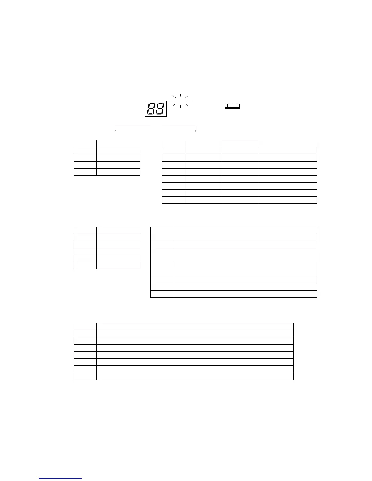
<Outdoor unit operation monitoring function>
The operation status and check code contents can be ascertained by means of the 2-digit number and symbol on digital
display light emitting diode LED2 by operating DIP switch SW2.
<Description of operation of digital display light emitting diode (LED2)>
• When ON (normal operation): Displays the operation mode.
OFF
ON
123456
(Load status)
• When blinking (Operation stopped by tripping protection device): Displays the check mode
[Tens digit: Operation mode]
Display Operation mode
O stopped
C Cooling/Dry
H Heating
d Defrost
[Units digit: Relay output]
• PUH-7, 8, 10MYF
Display Check contents (at power on)
E8 Indoor-outdoor communication receive abnormal (outdoor unit)
E9 Indoor-outdoor communication send abnormal (outdoor unit)
EA
Indoor/outdoor connection erroneous wiring, number of indoor
units mismatch
Eb
Indoor/outdoor connection erroneous wiring (indoor unit power
failure, disconnection)
Ed Serial communication abnormal (M-NET)
E0-E7 Communication other than outdoor unit abnormal
F8 Input circuit faulty
Display Check contents (operating)
U2 Compressor discharge temperature abnormal, CN23 short-circuit connector unplugged
U3 Compressor discharge temp thermistor (TH2) open/short
U4 Liquid temp thermistor (TH1), Condenser/evaporater temp thermistor (TH3) open/short
U6 Compressor overcurrent protection trip (51C trip), (49C trip)
UE High pressure protection (63H1 trip)
P1-P8 Indoor unit abnormal
A0-A8 M-NET communication abnormal
ON
SW2
LED2
 Loading...