OPERATING PROCEDURE
PHOTOS & ILLUSTRATIONS
Be careful when removing heavy parts.
6. Removing the electrical box
(1) Remove the electrical box cover (See Photo 1 and 2)
and the connectors (Refer to procedure 5).
(2) Remove the electrical box fixing screws (M5×10: 2
screw). (See Photo 3)
<Electrical parts in the electrical box>
• Terminal block for earth and reactor
• Indoor controller board
• Thermistor (TH)
(3)
Remove the electrical box (2 hooks).
Rubber mount
Note: When re-attaching the motor mount, make sure that the thicker
end faces the motor shaft.
45
8. Removing the fan motor (MF)
(1) Remove the turbo fan. (See Photo 7 and refer to proce-
dure 7)
(2) Remove the lead cover (tapping screw 4×10: 2 screws).
(See Photo 10)
(3) Loosen the 2 clamps.
(4) Remove the 3 nuts and washers (M5) .
(5) Remove the fan motor.
(6) Remove the 3 rubber mounts.
7. Removing the turbo fan
(1) Remove the electrical box. (See Photo 3 and refer to
procedure 6)
(2) Remove the bell mouth (tapping screw 4×10: 2 screws).
(See Photo 5)
(3) Remove the nut and washer (1 nut). (See Photo 7 and 8)
(4) Remove the turbo fan.
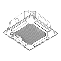
Photo 6
Photo 9
Photo 7
Photo 8
Photo 10
Electrical box
Bell mouth fixing screws
Bell mouth
Turbo fan
Nut and washer
Clamps
(2 points)
Lead cover
Coil plate
Lead cover
xing screws
Fan motor
Nuts and washers
Rubber mounts
Figure 3: Partial cross section
Rubber mount
Washer and nut
Fan motor
Turn this way to tighten.
Turn this way to loosen.
(The same directions as the fan rotation.)
Note: When re-attaching the motor mount, make sure that the
thicker end faces the motor shaft.
Hooks
 Loading...