OPERATING PROCEDURE
PHOTOS & ILLUSTRATIONS
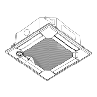
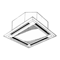
9. Removing the panel
(1) Remove the electrical box fixing cover. (See Photo 1)
(2) Disconnect the connector for vane motor (CNV: White).
(Refer to procedure 5)
(3) Loosen the 4 corner panel fixing screws (tapping screw
4×16). (See Figure 4)
(4) Slide the corner panel to the direction of the arrow 1,
and remove the corner panel. (See Figure 4)
(5) Remove the 4 installation screws (M5×28). (See Photo
11)
(6) Release the 2 temporary hanging hooks to remove the
grille
. (See Photo 12)
10. Removing the drain pan
(1) Remove the electrical box. (See photo 3 and refer to
procedure 6)
(2) Remove the bell mouth (tapping screw 4×10 : 2 screws).
(See Photo 6)
(3) Remove the drain pan (screw M5×10: 4 screws).
Installation
screw
Photo 11
Photo 12
Corner panel
①
①
Corner panel
Close-up
Screw
Grille
Temporary hanging hook
Photo 13
Drain pan
Figure 4
Drain pan
fixing screws
Drain pan
fixing screws
 Loading...