118
OPERATING PROCEDURE PHOTOS
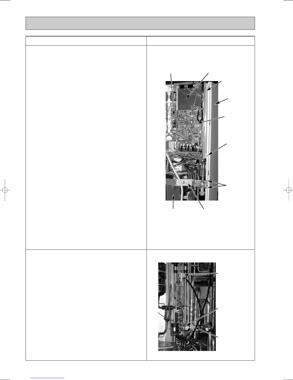
5. Electrical parts box disassembly procedures:
[PUMY-125VM, PUMY-125YM, PUMY-125YMA]
(1) Remove the side panel (Refer to 1)
(2) Remove the top panel (Refer to 1)
(3) Disconnect the following wires from the
multi controller board.
• Thermistor (Discharge temperature detection):TH1
• Thermistor (Low pressure saturated temperature
detection):TH2
• Thermistor (Pipe temperature defection • judging
defrost):TH5
• Thermistor (Outdoor temperature detection): TH6
• High-pressure sensor (Discharge pressure
detection): 63HS
• Expansion valve: SLEV
(4) Remove the board plate.
(5) Disconnect the following wires from the power supply
board:
• Fan motor: MF1 and MF2
• Solenoid coil: SV1
• 4-way coil: 21S4
Pull wires out of the electrical box after disconnecting them.
(6) After removing the connector cover, remove the compressor
wire and the inner thermostat terminal.
(7) Remove the electrical box screw (1 pc : 4 o 10).
(8) Remove the valve bed screws from the right side of
the valve bed (2 pcs : 4 o 10).
(9) Remove the electrical box after slightly loosening the
rear panel. The electrical box is held by two claws on
the left and one on the right.
6. Solenoid coil
ww
1 and 4-way coi
ww
2 disassembly
procedures:
(1) Remove the side panel (Refer to 1).
(2) Remove the top panel (Refer to 1).
(3) Remove the electrical parts box (Refer to 4 or 5).
(4) Remove coil screws (Solenoid coil w1 : 1 pc M4x6;
4-way coil w2 : 1 pc M5x6), and remove the solenoid
coil (SV1) w1 and 4-way coil (21S4) w2 wires from the
power supply board w3
Only PUMY-125VMA model w1 Solenoid valve (21S4)
w2 4-way valve (21S4)
w3 Power circuit board
Photo 6
PUMY-125VM, PUMY-P125YM, PUMY-P125YMA
(The electrical parts box in the picture below air for
PUMY-125YM and PUMY-125YMA.)
Photo 7
Power supply board
Electric
parts box
screw
Rear panel
Electrical
parts box
Multi controller
board
Valve bed
screws
Connector cover Valve bed
4-way valve
4-way coil w2
Solenoid coil w1
Board plate
OC183E--4.qxp 10.5.6 0:54 PM Page 118
 Loading...


