EasyManuals Logo

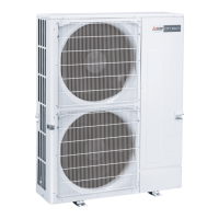
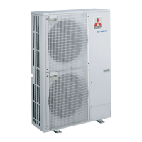
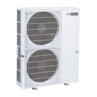
Mitsubishi PUMY-71VM User Manual

Mitsubishi PUMY-71VM
136 pages
To Next Page IconTo Next Page
To Previous Page IconTo Previous Page
Page #124 background imageLoading...
Page #124 background image
124
ELECTRICAL PARTS
PUMY-71VM
PUMY-71VM1
PUMY-71VM2
Part numbers that are circled are not shown in the figure.
3
5
2
14
8
11
VARISTOR 7
12
13
10
6
18
4
19
1
16
15
9
17
1
2
3
4
5
6
7
8
9
10
11
12
13
14
15
16
17
18
19
20
21
22
Part No. Specification
No.
Wiring
Diagram
Symbol
Recom-
mended
Q
,
ty
Price
Unit
Amount
Part Name
Q
,
ty/set
PUMY-71
VM
Remarks
(Drawing No.)
FAN MOTOR CAPACITOR
FAN MOTOR CAPACITOR
FUSE
POWER SUPPLY BOARD
FUSE
MULTI CONTROLLER BOARD
INTELLIGENT POWER MODULE
VARISTOR
DIODE STACK
CURRENT DETECTION
NOISE FILTER
FUSE HOLDER
FUSE
TERMINAL BLOCK
TERMINAL BLOCK
REACTOR
CAPACITOR
RESISTOR
MAGNETIC CONTACTOR
CAPACITOR
RESISTOR
THERMISTOR
RELAY
3.5µF 440VAC
3.0µF 440VAC
2A 250V
6A 250V
30A 250V
3P(M1,M2,S)
3P (L,N,;)
CE85˚C, 400V
LY-2F 230V
2
1
1
1
1
1
1
2
1
1
1
1
2
1
1
1
1
1
1
1
1
C1,C2
C1,C2
FUSE1
FUSE2
IPM
ZNR
DS
AC,CT
NF1
FUSE
TB3,7
TB1
DCL
C3
R1
52C
C5
R2
THHS
X4
R01 580 255
R01 576 255
R01 527 239
R01 35A 311
R01 005 239
T7W E06 315
R01 35A 314
R01 V47 349
R01 W06 292
T7W E00 365
R01 35A 346
R01 35A 241
R01 272 239
T7W A12 716
T7W A13 716
R01 35A 259
T7W E02 254
R01 W04 234
R01 272 215
T7W E01 254
R01 35A 233
R01 36A 202
T7W 737 215
VM
1 VM2
2
1
1
1
1
1
1
2
1
1
1
1
2
1
1
1
1
1
1
1
1
2
1
1
1
1
1
1
2
1
1
1
1
2
1
1
1
1
1
1
1
1
1
OC183E--5.qxp 10.5.6 1:06 PM Page 124

Questions and Answers:

Question and Answer IconNeed help?

Do you have a question about the Mitsubishi PUMY-71VM and is the answer not in the manual?

Mitsubishi PUMY-71VM Specifications

General IconGeneral
BrandMitsubishi
ModelPUMY-71VM
CategoryAir Conditioner
LanguageEnglish

Related product manuals