49
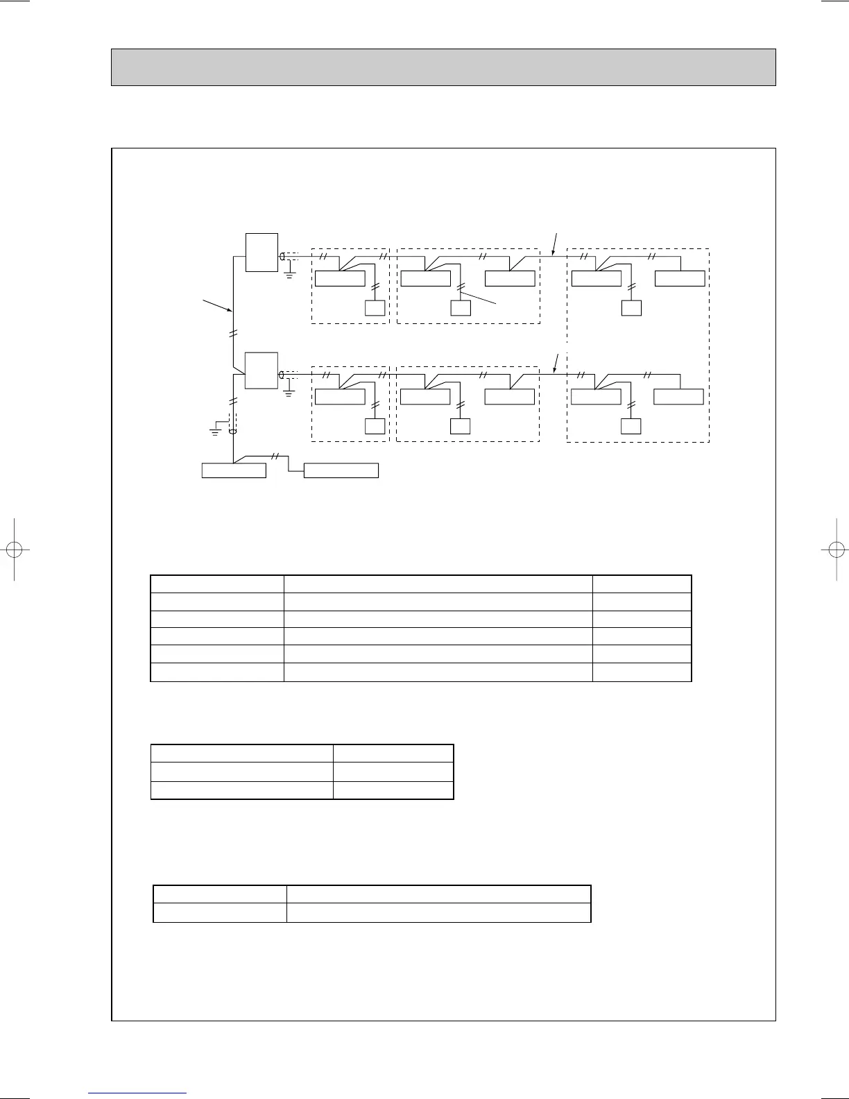
7-3-2. System Controller (SC) to Perform Centralized Control
<Example of System Arrangement>
The following diagram shows the use of system controller (SC) to control a system that includes the multiple outdoor unit.
Transmission
wire for central-
ized control
<Room A>
For transmission
wire
PAC-SC33KUA
PAC-SC34KUA
<Room B>
<Room D> <Room E>
<Room C>
Outdoor
unit
Indoor unit
A
Indoor unit Indoor unit Indoor unit
Remote controller network
Remote control
wire
Indoor • outdoor transmission wire (Shielded wire)
SC: Centralized controller, linked system control board, group remote controller, etc.
A : M-NET or MA remote controller
(Coexistence of M-NET remote controller and MA remote controller is not admitted in the same system.)
Indoor unit
Indoor unitIndoor unitIndoor unitIndoor unitIndoor unit
Power supply installation
System controller
Outdoor
unit
Indoor • outdoor transmission wire (Shielded wire)
A
A
A
AA
Note 1) The NR, SC, indoor and outdoor unit all require address settings.
ww
The address automatically becomes “100” if it is set as “01~50”. (PUMY-125VMA, PUMY-125VMA
1)
2) Indoor unit that may be connected with an SC are shown as follows.
3) There may be a maximum of two controllers when a group has 16 indoor units or less.
4) The transmission wire must have a power supply when an SC is used. Please connect the power supply for
the transmission wire to the centralized controller transmission wire.
5) Use the shielded wire of at least 1.25mm
2
for the indoor, outdoor, and centralized controller transmission
wires. In addition, all shielded wires in a system must be grounded at one point. If the length of the remote
control wire exceeds 10m, use an insulated wire for the extra portion.
Indoor unit
Outdoor unit
M-NET Remote controller (Main)
M-NET Remote controller (Sub)
SC
MA Remote controller
Linked settings must be made within a group.
The lowest address of an indoor unit within a refrigerant system is +50.
The lowest address of an indoor unit within a group is +100.
The address of the main remote controller is +50.
Unnecessary address setting (Necessary main/sub setting)
1 ~ 50
51 ~ 100
101 ~ 150
151 ~ 200
0 or 201 ~ 250
—
Centralized controller
Multi-unit controller board
Group controller
50 group /50 units
24 group /50 units
8 group /16 units
SC with 2 units or less
SC with 3 to 5 units
Power supply for transmission wire PAC-SC33KU
Power supply for transmission wire PAC-SC34KU
W
OC183E--2.qxp 10.5.6 0:47 PM Page 49

 Loading...


