57
• Name, Symbol, and the Maximum Units for Connection
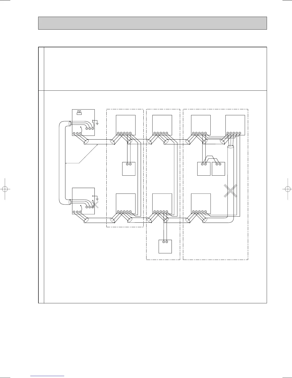
Permissible Length
Prohibited items
• Max length via outdoor units : L1+L2+L3+L4+L5+L6+L7+L9
L1+L2+L3+L4+L5+L6+L8+L9 [ 500 meters (1.25mm
2
)
• Max transmission cable length : L
1+L2+L3+L4, L5+L6+L7, L5+L6+L8, L7+L8
[ 200 meters (1.25mm
2
)
• Remote controller cable length : R
1,R2, R3, R4 [ 10 meters (0.5 to 0.75mm
2
)
If the length exceeds 10 meters, use a 1.25 mm
2
shielded wire. The length of this sec-
tion (L
8) should be included in the calculation of the maximum length and overall length.
• The terminal S on the terminal block (TB7) for the central control panel should be connected to the ground terminal ;
of the electric components box for one outdoor unit only.
• Never connect together the terminal blocks (TB5) for transmission wires for indoor units (IC) that have been connected to
different outdoor units (OC).
• M-NET remote controller and MA remote controller cannot be connected with the indoor unit of the same group wring
together
M1 M2 S
TB7
IC
(051)
M1 M2 S 1 2 1 2 1 2
TB5 TB15
12
TB15 TB15 TB15
MA
Shielded wire
(001)
IC
M1 M2 S
TB5
(002)
IC
M1 M2 S
TB5
(004)
IC
M1 M2 S
TB5
(003)
IC
M1 M2 S
TB5
(005)
IC
M1 M2 S
TB5
(007)
IC
Group 1 Group 3 Group 5
M1 M2 S
TB5
(006)
MA
MA
MA
CN40
OC
M1 M2 S
TB7
(052)
OC
M1 M2 S
TB3
M1 M2 S
TB3
1212
TB15 TB15
12
TB15
OC183E--2.qxp 10.5.6 0:47 PM Page 57

 Loading...


