99
31
32
33
34
35
36
37
38
64
65
66
67
68
69
70
71
72
73
74
75
76
77
78
80
81
82
83
84
85
86
87
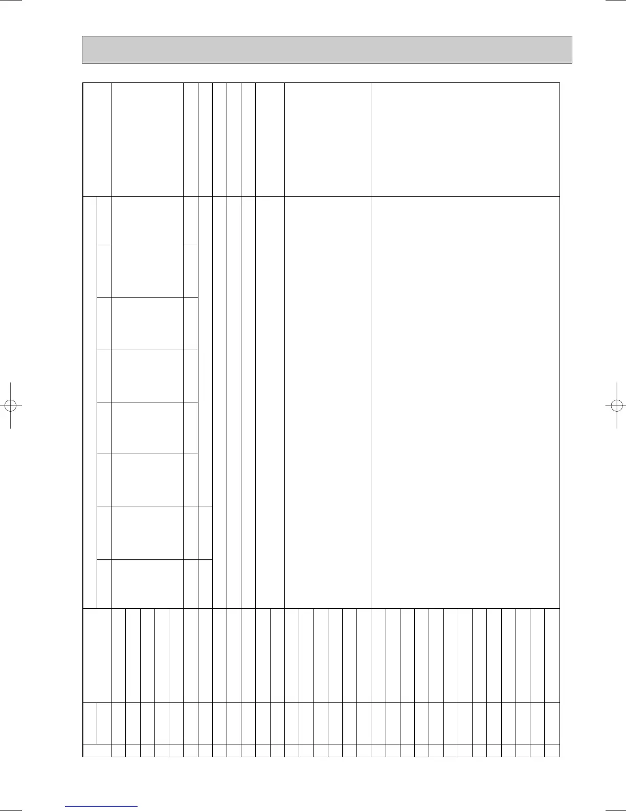
SW1 setting
12345678
11111000
00000100
10000100
01000100
11000100
00100100
10100100
01100100
00000010
10000010
01000010
11000010
00100010
10100010
01100010
11100010
00010010
10010010
01010010
11010010
00110010
10110010
01110010
00001010
10001010
01001010
11001010
00101010
10101010
01101010
11101010
Indoor unit mode (No. 1 unit)
Indoor unit mode (No. 2 unit)
Indoor unit mode (No. 3 unit)
Indoor unit mode (No. 4 unit)
Indoor unit mode (No. 5 unit)
Outdoor unit operational mode
External connection status
Communication demand capacity
Operational frequency
Target frequency
Outdoor fan control step number
EER fan control step number (cooling)
Outdoor SLEV opening
Indoor LEV opening (No.1 unit)
Indoor LEV opening (No.2 unit)
Indoor LEV opening (No.3 unit)
Indoor LEV opening (No.4 unit)
Indoor LEV opening (No.5 unit)
High-pressure sensor (Pd)
TH1(Td)
TH2(ET)
TH6
TH5
THHS
TH23 (No.1 indoor unit)
TH23 (No.2 indoor unit)
TH23 (No.3 indoor unit)
TH23 (No.4 indoor unit)
TH23 (No.5 indoor unit)
TH22 (No.1 indoor unit)
TH22 (No.2 indoor unit)
1
2
3
4
7
5
6
8
•Display of indoor unit
operating mode
Light on/light off
Input: light off No input: light on
Display of communication demand capacity
Display of actual operating frequency
Display of target frequency
Display of number of outdoor
fan control steps (target)
Display of openness (pulses) of
outdoor SLEV and indoor LEV
Display of outdoor subcool
(SC) data and detection data
from high-pressure sensor and
each thermistor
Notes
0~255
0~FF(16 progressive)
0~255
0~20
0~2000
OFF Fan
Cooling
thermo
ON
Cooling
thermo
OFF
Heating
thermo
ON
Heating
thermo
OFF
ON/OFF
Heating/Cooling
Abnormal/Normal
DEFROST/NO
Refrigerant pull back/no
Excitation current/no
3-min.delay/no
Demand junction
Night mode
power/no
Display mode
Display on the LD1 (display data)
-99.9 ~ 999.9 (short circuit/open: -99.9 or 999.9)
No.
OC183E--4.qxp 10.5.6 0:54 PM Page 99
 Loading...


