3
SEQUENCE PROGRAM CONFIGURATION AND
EXECUTION CONDITIONS
3.1 Sequence Program
3
- 4
1
Overview
2
Performance
Specification
3
Sequence Program
Configuration and
Execution Conditions
4
I/O Nunber Assignment
5
Memories and Files
Handled by CPU Module
6
Functions
7
Communication with
Intelligent Function
Module
8
Parameters
(1) Sequence program description method
There are two different methods for describing sequence programs: ladder mode and
list mode.
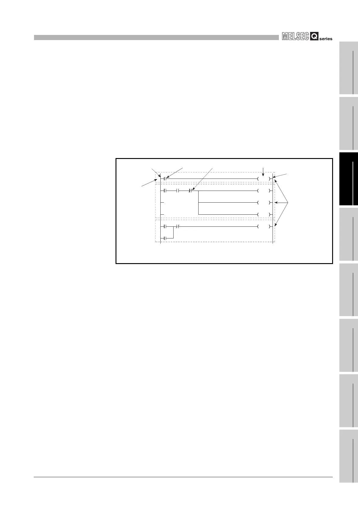
(a) Ladder mode
The ladder mode is based on the concept of a sequence circuit of relay control. It
enables programming in representation close to a sequence circuit.
In the ladder mode, programming is performed in ladder block units.
A ladder block is the minimum unit for performing sequence program operation,
which starts from the left side vertical bus bar and ends at the right side vertical
bus bar.
(b) List mode
In the list mode, the contacts and coils indicated by symbols in the ladder mode
are programmed using dedicated instructions.
The following instructions are used for N/O contacts (a contact), N/C contacts (b
contact) and coils.
• N/O contact • • • LD,AND,OR
• N/C contact • • • LDI,ANI,ORI
• Coil • • • • • • • • OUT
Diagram 3.4 Ladder mode
Y21
Y22
Y23
Y24
Y20
Y24
0
2
8
Left side vertical bus bar N/O contact N/C contact Coil (output)
Right side
vertical bus bar
Ladder block
Step number
X0 to 5 indicate inputs.
Y20 to 24 indicates outputs.
X0
X3
X4 X5
X1 X2
 Loading...

