57
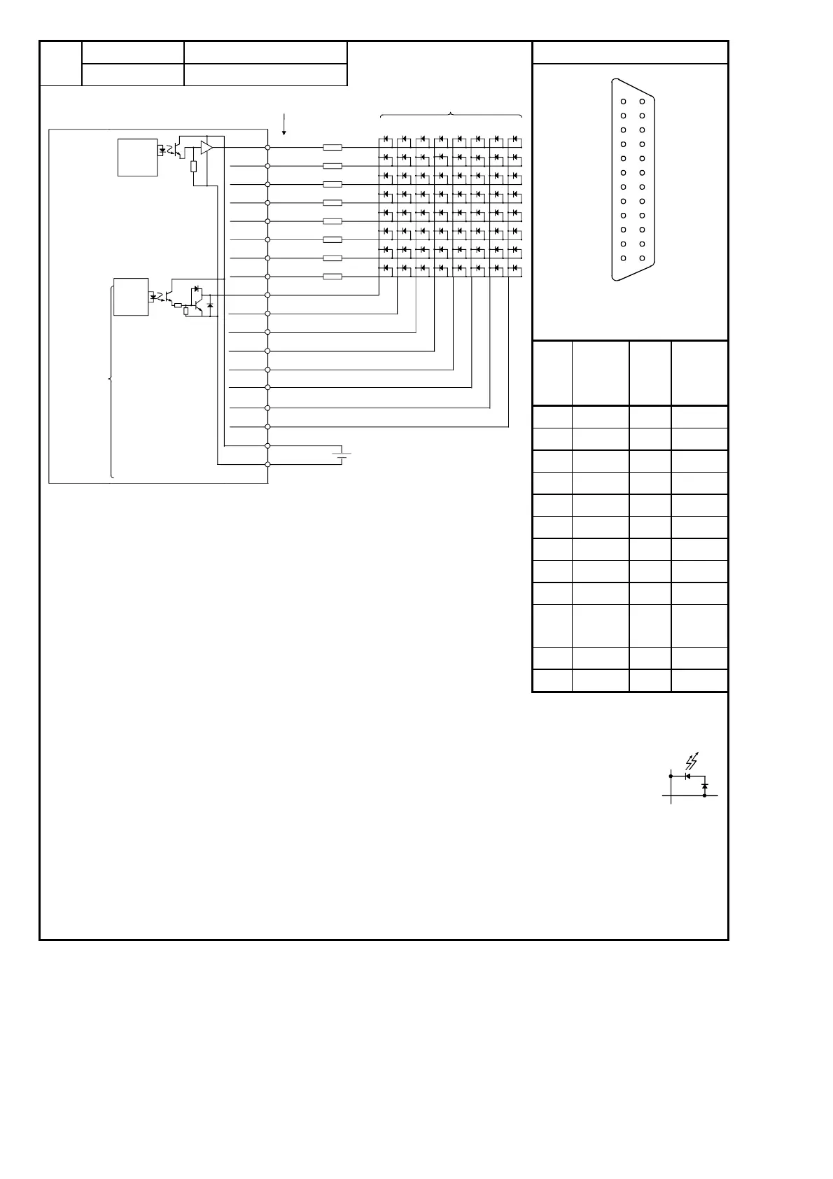
Model Rated Load Voltage Pin Arrangement
(18)
A1S42Y 12/24 VDC
B12
B11
B10
B9
B8
B7
B6
B5
B4
B3
B2
A12
A11
A10
A9
A8
A7
A6
A5
A4
A3
A2
B1 A1
Seen from front
face of the module
Pin
No.
Signal
Name
(F
H)
Pin
No.
Signal
Name
(F
H)
B12 YD0 A12 YD1
B11 YD2 A11 YD3
B10 YD4 A10 YD5
B9 YD6 A9 YD7
B8 YSCN0 A8 YSCN1
B7 YSCN2 A7 YSCN3
B6 YSCN4 A6 YSCN5
B5 YSCN6 A5 YSCN7
B4 Vacant A4 Vacant
B3
12/24
VDC
A3
12/24
VDC
B2 0V A2 0V
B1 Vacant A1 Vacant
Y38
B12
A12
B11
A11
B10
A10
B9
A9
B8
A8
B7
A7
B6
A6
B5
A5
YD0
YD1
YD2
YD3
YD4
YD5
YD6
YD7
YSCN0
YSCN1
YSCN2
YSCN3
YSCN4
YSCN5
YSCN6
YSCN7
B3A3
B2A2
Y30Y28Y20Y18Y10Y08Y00
Y39Y31Y29Y21Y19Y11Y09Y01
Y3AY32Y2AY22Y1AY12Y0AY02
Y3BY33Y2BY23Y1BY13Y0BY03
Y3CY34Y2CY24Y1CY14Y0CY04
Y3DY35Y2DY25Y1DY15Y0DY05
Y3EY36Y2EY26Y1EY16Y0EY06
Y3FY37Y2FY27Y1FY17Y0FY07
12/24 VDC
A1S42Y
*3
Resistors to limit
LED current
R
R
R
Internal
control
circuit
Internal
scanning at
1/8th duty
Output terminals
Pin No.
Internal
control
circuit
*3 Mount the resistors to limit
LED current externally to the
A1S42Y.
*1 The fuse in the output module is provided to
prevent the external wiring from burning in
the event of a short circuit in the module’s
output. Consequently, it may not be able to
protect output devices.
If an output device is damaged in a failure
mode other than a short circuit, the fuse
might not be blown.
*2 The "ERR." LED will alxo come ON when
the external power supply is cut.
*4 The power supply voltage (12/24VDC) is
applied in the LED’s reverse direction.
If the peak inverse voltage is insufficient,
connect protective diodes in series with
each of the LEDs.
 Loading...
