7
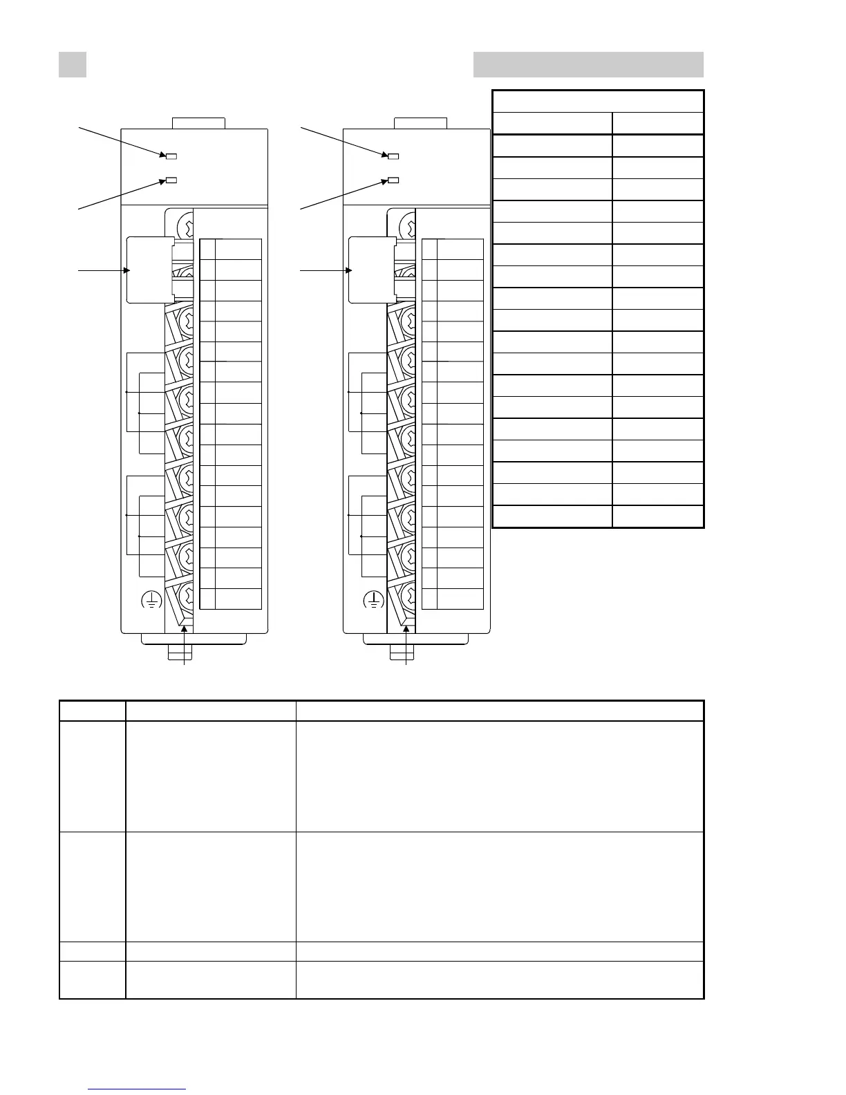
4. NAMES AND SETTINGS OF THE PARTS
Terminal Block Layout
Terminal number Signal name
1RTD +
2
3RTD -
4
5
6 CH1 SLD
7 CH2 SLD
8 CH1 +
9 CH2 +
10 CH1 -
11 CH2 -
12 CH3 +
13 CH4 +
14 CH3 -
15 CH4 -
16 CH3 SLD
17 CH4 SLD
18 FG
1)
2)
Q64TD
RUN
ERROR
1
2
3
4
5
6
7
8
9
10
11
12
13
14
15
16
17
18
R
T
D
CH1+
CH2+
1-
2-
SLD
SLD
CH3+
CH4+
3-
4-
SLD
SLD
(FG)
Q64TD
3)
4)
1)
2)
Q64TDV-GH
RUN
ERROR
1
2
3
4
5
6
7
8
9
10
11
12
13
14
15
16
17
18
R
T
D
CH1+
CH2+
1-
2-
SLD
SLD
CH3+
CH4+
3-
4-
SLD
SLD
(FG)
Q64TDV
-GH
3)
4)
Q64TD
Q64TDV-GH
Number Name and Appearance Description
1) RUN LED
Indicates the operating status of the Q64TD/Q64TDV-GH.
On : Operating normally.
Flicker : Offset/gain setting mode
Off : 5V power-off , Watchdog timer error occurrence or
module change enabled status during online module
change
2) ERR LED
Indicates the error status of the Q64TD/Q64TDV-GH.
On : Error occurrence
Flicker : Switch setting error
Switch 5 was set to other than 0 in intelligent function
module switch setting of GX Developer.
Off : Operating normally.
3) Terminal block Used for wiring of the thermocouple, etc.
4)
Cold junction temperature
compensation resistor
Used for cold junction temperature compensation using Pt100.
 Loading...

