8
5. WIRING
5.1 Wiring Instructions
(1) Use separate cables for the AC control circuit and Q64TD/Q64TDV-GH's
external input signals to avoid the influence of AC side surges and
inductions.
(2) Always place the thermocouple/micro voltage signal cable at least 100mm
away from the main circuit cables and AC control circuit lines.
Fully keep it away from high-voltage cables and circuits which include
harmonics, such as an inverter's load circuit. Not doing so will make the
module more susceptible to noises, surges and inductions.
(3) Insulation-sleeved crimping terminals cannot be used with the terminal
block.
It is recommended to fit mark tubes or insulation tubes to the wire
connection parts of the crimping terminals.
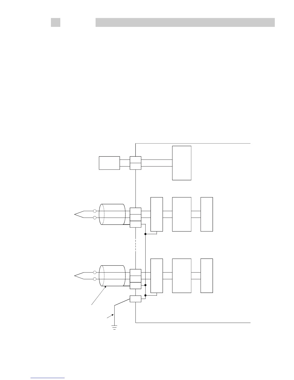
5.2 External Wiring
(1) Thermocouple
RTD
Input
amplifier
CH1
Filter
Transformer
CH4
Pt100
*1
*2
*1:As cables, always use shielded compensation conductors.
Also, wire the shielded cables as short as possible.
*2:Always connect to the earth terminal of the control box.
+
-
SLD
SLD
FG
Input
amplifier
Input
amplifier
Filter
Transformer
+
-
+
-
 Loading...

