12 - 33
MELSEC-Q
12 CONTROL SUB FUNCTIONS
(5) During simultaneous start, a stroke limit check is carried out for the current
values of every axis to be started. Every axis will not start if an error occurs,
even if it only occurs in one axis.
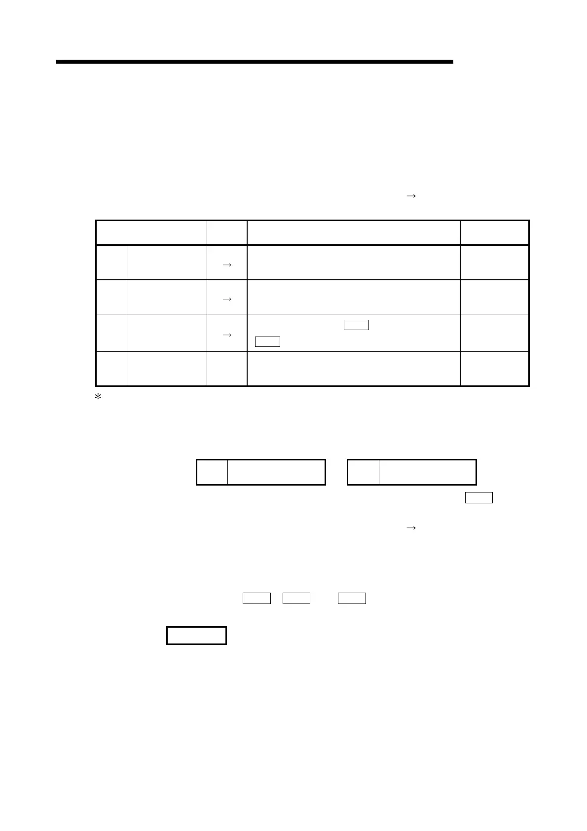
[5] Setting the software stroke limit function
To use the "software stroke limit function", set the required values in the
parameters shown in the following table, and write them to the QD75.
The set details are validated at the rising edge (OFF
ON) of the PLC READY
signal (Y0).
Setting item
Setting
value
Setting details
Factory-set
initial value
Pr.12
Software stroke
limit upper limit
value
Set the upper limit value of the moveable range. 2147483647
Pr.13
Software stroke
limit lower limit
value
Set the lower limit value of the moveable range. –2147483648
Pr.14
Software stroke
limit selection
Set whether to use the "
Md.20
Current feed value" or
"
Md.21
Machine feed value" as the "current value".
0: Current feed
value
Pr.15
Software stroke
limit valid/invalid
setting
0:Valid
Set whether the software stroke limit is validated or
invalidated during manual control (JOG operation,
Inching operation, manual pulse generator operation).
0: valid
Refer to section "5.2 List of parameters" for setting details.
[6] Invalidating the software stroke limit
To invalidate the software stroke limit, set the following parameters as shown,
and write them to the QD75.
Pr.12
Software stroke limit
upper limit value
= Pr.13
Software stroke limit
lower limit value
(For manual operation, set "0: software stroke limit invalid" in the "
Pr.15
Software stroke limit valid/invalid setting".)
The set details are validated at the rising edge (OFF
ON) of the PLC READY
signal (Y0).
When the unit is "degree", the software stroke limit check is not performed during
speed control (including speed control in speed-position switching control or
position-speed switching control) or during manual control, independently of the
values set in
Pr.12
,
Pr.13
and
Pr.15
.
REMARK
•
Parameters are set for each axis.
•
It is recommended that the parameters be set whenever possible with GX
Configurator-QP. Execution by sequence program uses many sequence programs
and devices. The execution becomes complicated, and the scan times will
increase.
 Loading...