12 - 36
MELSEC-Q
12 CONTROL SUB FUNCTIONS
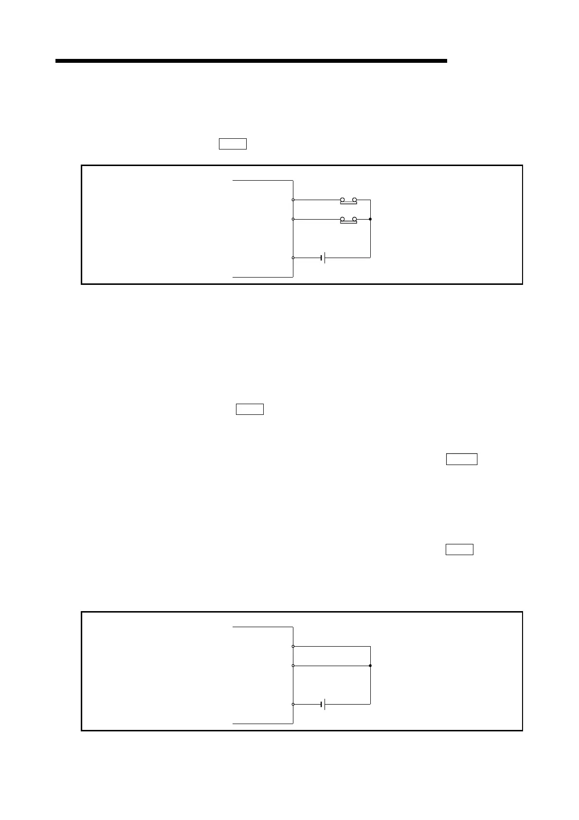
[2] Wiring the hardware stroke limit
When using the hardware stroke limit function, wire the terminals of the QD75
upper/lower limit stroke limit as shown in the following drawing.
(When "
Pr.22
Input signal logic selection" is set to the initial value)
QD75
FLS
RLS
COM
24VDC
Fig. 12.20 Wiring when using the hardware stroke limit
[3] Precautions during control
(1) If the machine is stopped outside the QD75 control range (outside the
upper/lower limit switches), or if stopped by hardware stroke limit detection,
the "OPR control", "major positioning control", and "high-level positioning
control" cannot start. To carry out these types of control again, return the
workpiece to the QD75 control range by a "JOG operation", "inching
operation" or "manual pulse generator operation".
(2) When "
Pr.22
Input signal logic selection" is set to the initial value, the
QD75 cannot carry out the positioning control if FLS (limit switch for upper
limit) is separated from COM or RLS (limit switch for lower limit) is separated
from COM (including when wiring is not carried out).
(3) When the control unit is "degree" (when "degree" is set in "
Pr.1 Unit
setting"), the manual control software stroke limit is invalidated (a stroke limit
check is not carried out).
[4] When the hardware stroke limit function is not used
When not using the hardware stroke limit function, wire the terminals of the QD75
upper/lower limit stroke limit as shown in the following drawing.
When the logic of FLS and RLS is set to "positive logic" using "
Pr.22
Input
signal logic selection", positioning control can be carried out even if FLS and RLS
are not wired. (For details, refer to "Section 13.4 External I/O signal logic
switching function".)
QD75
FLS
RLS
COM
24VDC
Fig. 12.21 Wiring when not using the hardware stroke limit function
 Loading...