-
20
-
'16 • SCM-T-199
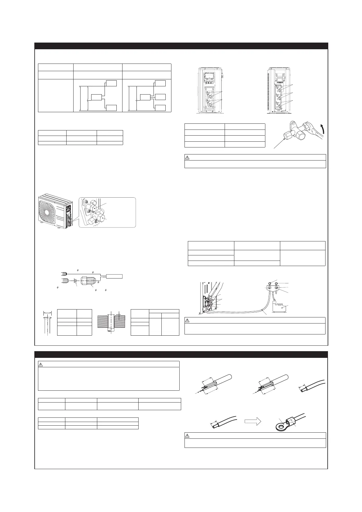
4. CONNECTING PIPING WORK
1. Restrictions on unit installation
Abide by the following restrictions on unit installation.
Improper installation can cause compressor failure or performance degradation.
Model SCM40/45 Model SCM50/60
piping length
one indoor unit MAX 25m
all indoor unit MAX 30m
one indoor unit MAX 25m
all indoor unit MAX 40m
hight difference
MAX
25m
MAX 15m
MAX 15m
outdoor
unit
indoor
unit
indoor
unit
MAX
25m
MAX 15m
MAX 15m
outdoor
unit
indoor
unit
indoor
unit
indoor
unit
2. Preparation of connecting pipe
2.1. Selecting connecting pipe
Select connecting pipe according to the following table.
Indoor unit Model 20/25/35 Model 50/60
Gas pipe ø9.52 ø12.7
Liquid pipe ø6.35 ø6.35
• Pipe wall thickness must be greater than or equal to 0.8 mm.
• Pipe material must be O-type (Phosphorus deoxidized seamless copper pipe ICS 23.040.15, ICS
77.150.30).
2.2. Cutting connecting pipe
(1) Cut the connecting pipe to the required length with pipe cutter.
(2) Hold the pipe downward and remove the burrs. Make sure that no foreign material enters the pipe.
(3) Cover the connecting pipe ends with the tape.
3. Piping work
Check that both liquid and gas operation valves are fully closed.
Carry out the piping work with operation valves fully closed.
Liquid service valve
Gas service valve
3.1. Flaring pipe
(1) <SCM40/45>
Takeoutarenutsfromtheservice valves of outdoor unit and engage them onto connecting pipes.
<SCM50/60>
Takeoutarenutsfromtheservice valves of outdoor unit.
Ifa5.0,6.0kwclassindoorunit(gassidepipe12.7)isgoingtobeconnectedtotheservice valves
(9.52), variable joints available as accessories must be applied to the gas side service valves.
Securelytthecopperpackingbetweentheservice valve and the variable diameter joint to
prevent shifting.
Engagearenutsontoconnectingpipes.
vice
alve
Liquid side service valve ( 6.35)
6.35 pipe
50,60 model
Indoor unit
Gas side service
valve (
9.52)
Copper packing
Variable diameter joint
12.7 pipe
(2) Flarethepipesaccordingtotableandgureshownbelow.
Flare dimensions for R410A are different from those for conventional refrigerant.
AlthoughitisrecommendedtousethearingtoolsdesignedspecicallyforR410A,conventionalaring
toolscanalsobeusedbyadjustingthemeasurementofprotrusionBwithaareadjustmentgauge.
Copperpipe
outer diameter
A
0
–0.4
Copperpipe
outer diameter
Rigid (clutch) type
R410A Conventional
ø6.35 9.1 ø6.35
0-0.5 1.0-1.5
ø9.52 13.2 ø9.52
ø12.7 16.6 ø12.7
3.2. Connecting pipes
(1) Connect pipes on both liquid and gas sides.
<SCM40/45> <SCM 50/60>
Service valve
for room B
Service valve
for room A
Service valve
for room C
Service valve
for room B
Service valve
for room A
(2)Tightennutstospeciedtorqueshowninthetablebelow.
Service valve size (mm) Tightening torque (N·m)
ø6.35 (1/4") 14-18
ø9.52 (3/8") 34-42
ø12.7(1/2") 49-61
Do not hold the valve cap area with a spanner
CAUTION
•Donotapplyrefrigeratingmachineoiltothearedsurface.Itcancauserefrigerantleakage.
•Donotapplyexcesstorquetothearednuts.Thearednutsmaycrackresultinginrefrigerantleakage.
4. Evacuation
(1) Connect vacuum pump to gauge manifold. Connect charge hose of gauge manifold to a service port
of outdoor unit.
(2)Runthevacuumpumpforatleastonehourafterthevacuumgaugeshows-0.1MPa(–76cmHg).
(3)Conrmthatthevacuumgaugeindicatordoesnotriseevenifthesystemisleftfor15minutesormore.
Vacuum gauge indicator will rise if the system has moisture left inside or has a leakage point.
Check the system for the leakage point. If leakage point is found, repair it and return to (1) again.
(4) Close the Handle Lo and stop the vacuum pump.
Keep this state for a few minutes to make sure that the compound pressure gauge pointer does not
swing back.
(5) Remove valve caps from liquid service valve and gas service valve.
(6) Turn the liquid service valve's rod 90 degree counterclockwise with a hexagonal wrench key to open
valve.
Close it after 5 seconds, and check for gas leakage.
Usingsoapywater,checkforgasleakagefromindoorunit'sareandoutdoorunit'sareandvalverods.
Wipe off all the water after completing the check.
(7)Disconnectcharginghosefromgasservicevalve'sserviceportandfullyopenliquidandgasservice
valves. (Do not attempt to turn valve rod beyond its stop.)
(8)Tightenservicevalvecapsandserviceportcaptothespeciedtorqueshowninthetablebelow.
Service valve size (mm)
Service valve cap tightening
torque (N·m)
Service port cap tightening
torque (N·m)
ø6.35 (1/4")
20-30
10-12ø9.52 (3/8")
ø12.7(1/2") 25-35
(9) Repeat the above steps (1) to (8) for all connected indoor units.
Handle Lo
Valve cap
Liquid service valve
Gas service valve
Service port
Pressure gauge
Gauge manifold
Handle Hi
Vacuum pump
CAUTION
• To prevent the entering of different oil into the refrigeration system, do not use tools designed for any
otherrefrigeranttype(R22,R407C,etc.).
•
Topreventvacuumpumpoilfromenteringintotherefrigerantsystem,useacounterowpreventionadapter.
5. ELECTRICAL WIRING WORK
WARNING
• Make sure that all the electrical work is carried out in accordance with the national or regional electri-
cal standards.
• Make sure that the earth leakage breaker and circuit breaker of appropriate capacities are installed
(Refer to the table given below).
• Do not turn on the power until the electrical work is completed.
• Do not use a condensive capacitor for power factor improvement under any circumstances.
(It does not improve power factor. Moreover, it can cause an abnormal overheat accident).
Breakerspecications
Model Phase Earth leakage breaker Circuit breaker
SCM40/45/50/60 Single phase
Leakage current: 30mA,
0.1sec or less
Over current: 25A
Mainfusespecication
Model Specication Parts No.
SCM40/45/50 250V 15A SSA564A136
SCM60 250V 20A SSA564A136A
1.Preparing cable
(1) Selecting cable
Selectthepowersourcecableandconnectingcableinaccordancewiththespecicationsmentionedbelow.
(a) Power source cable
3-core* 4.0mm
2
ormore,conformedwith60245IEC57(CENELECH05RN-F)
When selecting the power source cable length, make sure that voltage drop is less than 2%.
If the wire length gets longer, increase the wire diameter.
(b) Connecting cable
4-core* 1.5mm
2
,conformedwith60245IEC57(CENELECH05RN-F)
* 1 Earth wire is included (Yellow/Green).
(2) Arrange each wire length as shown below.
Make sure that each wire is stripped 10mm from the end.
<Power source cable> <Connecting cable> <Wire end>
40mm or more
40mm or more
e
(3) Attach round crimp-type terminal to each wire as shown in the below.
Selectthesize ofroundcrimp-type terminal after consideringthe specicationsofterminal blockandwire
diameter.
Round crimp-type terminal
Sleeve
CAUTION
Powersourcecableandconnectingcablemustconformtothespecicationsmentionedinthemanual.
Usingcableswithwrongspecicationsmayresultinunitmalfunction.
 Loading...