-
44
-
'16 • SCM-T-199
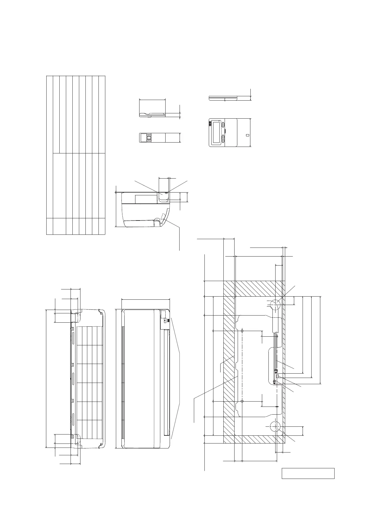
2.2 Exterior dimensions
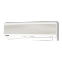
(1) Wall mounted type (SRK, SKM)
Models SRK20ZMX-S, 25ZMX-S, 35ZMX-S, 50ZMX-S
RKY000Z058
59.9
26
61.5
46.5
59.9
20.9
46.5
61.5
890
309
Outlet for down piping
(Refer to the above view)
(Service space)
Installation plate
50
120
220
48.9
222.5
48
58
D
B
E
35
35
650
450
120
100
220
7.9
70
295.4
5.7
48
54
C
491.1
520.8
559.1
A
46.5
19
60
24
61.5
120
9
61.5
F
G
3
220
Space for installation and service when viewing from the front
Unit
15(Service space)
(Service space)
(Service space)
Terminal block
Wired remote control
(Option)
Notes(1)The model name label is attached
on the underside of the panel.
(2)It takes the interface kit (SC-BIKN-E)
to connect the wired remote control.
Unit:mm
Wireless remote control
Hole on wall for right rear piping
Hole on wall for left rear piping
Gas piping
Outlet for wiring
Drain hose
Liquid piping
F
E
C
D
B
Symbol
A
(φ65)
VP16
φ6.35(1/4")(Flare)
Content
(φ65)
Outlet for piping(on both side)G
φ9.52(3/8")(Flare)
φ12.7(1/2")(Flare)
Model 20,25,35
Model 50
167
Hole on wall for right rear piping
Hole on wall for left rear piping
Gas piping
Outlet for piping(on both side)
Drain hose
F
E
C
D
Symbol
A
(φ65)
VP16
Content
(φ65)
SRK20, 25, 35 φ9.52(3/8")(Flare)
Wireless remote control
SRK50 φ12.7(1/2")(Flare)
Wired remote control
(Option)
φ6.35(1/4")(Flare)
Liquid piping
B
Space for installation and service when viewing from the front
Unit:mm
Notes(1)The model name label is attached
on the right side of the unit.
(2)To connect the wired remote control,
the interface kit(SC-BIKN-E)is required.
□120
19
60 24
167
45
45
870
290
Outlet for downward piping
(Refer to the top view)
230 3
6013
530
450
185
190
43
170
585
13
(Service space)
Unit
(Service space)
(Service space)
Installation board
142.5 142.5
100
50
9
47
268
47
80 100
Terminal block
60 3535 60
□120 19
210
55 55
537
528
SRK 50 :475
(Service space)
170
210
435 435
SRK 20,25,35 :469
45
F
D E
A
B
C
F F
 Loading...