-
218
-
'16 • SCM-T-199
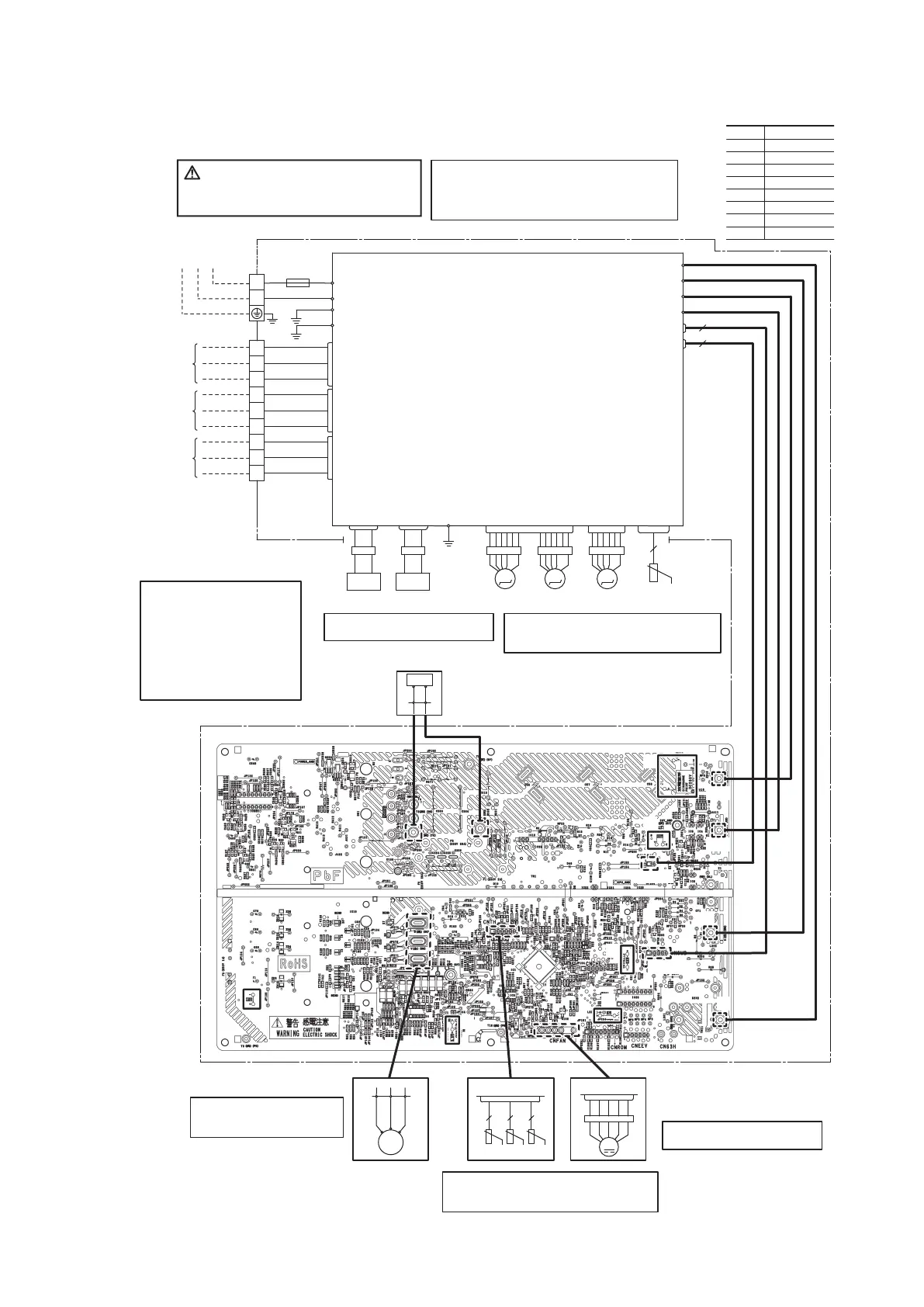
◆Inspection power transistor
Remove the fasten terminal and test
output voltage
◆Inspection of resistance value of sensor
Remove the connector and check the resistance value.
See the section of sensor characteristics on page
209.
BK
WH
RD
V WU
FMo
CM
CNTH
CNFAN
M
3~
M
T2
T1
L
OR
YE
2 2 2
t゜
t゜
t゜
Tho-R Tho-A Tho-D
S
R
SNSUB
S-2
C-2
CN20V
②
①
⑥
④
⑤
③
Model SCM50ZS-S
◆Inspection of resistance value of sensor
Remove the connector and check the resistance value.
See the section of sensor characteristics on page XX .
UNIT A
UNIT B
UNIT C
Power source
1 Phase
AC220-240V 50Hz
EEV A
BK
WH
WH
S-1
CNMAIN
S
IN
R
IN
BK
WH
S
O
R
O
250V 15A/
FUSE
CN20S
G2
Y/G
RD
C-1
CN20V
5
2
G1
Y/G
G
Y/G
CNEEV1
CNEEV3
CNTH
TB2
CNA
CNB
CNC
TB1
N
L
EEV B EEV C
Y/G
WH
BK
M
M
M
WH
RD
BL
PCB 2(SUB)
PCB 1(MAIN)
20S
HEATER
WH
RD
CNHEAT
250V 20A
3
2
1
BK
WH
RD
3
2
1
3
2
1
BK
WH
BR
BK
WH
BL
t゜
2
Tho-S
Color marks
Mark Color
BK
BR
Black
BL Blue
Brown
RD
Y/G
Red
Yellow/Green
WH White
OR Orange
YE Yellow
◆Inspection of outdoor fan motor
See page 219.
CAUTION- HIGH VOLTAGE
High voltage is produced in the control box. Don't touch
electrical parts in the control box for 5 minutes after the
unit is stopped.
◆Power source and serial signal inspection
① to ②: AC220/230/240V
② to ③ : Normal if the voltage oscillates between
DC0 and approx. 20V
◆Inspection of electronic expansion valve
See page 219.
Display Voltage range
◆Voltage check in PCB
The normal range is as follows.
①DC280V DC230V - DC310V
②DC220V DC218V - DC222V
③DC213V DC212V - DC214V
④DC215V DC214V - DC216V
⑤DC225V DC224V - DC226V
⑥DC 2.5V DC 2.3V - DC
2
2.5V

 Loading...