-
308
-
'16 • SCM-T-199
Names of recommended signal wires
Terminal
block for
Superlink
E board
Terminal
block for
iterface
Y
X
Y
X
DIP switch
(SW2-2)
●XR1- 4 are for the DC12V relay
●XR
5 is a DC12/24V or AC220-240V relay
●CnT connector (local) maker, model
Connector Molex 5264-06
Molex 5263TTerminals
DIP switch
(SW2-3)
DIP switch
(SW2-1)
Operation output
Output 1
Output 2
Output 3
Output 4
Input/
Output
ContentFunction
Relay ON/OFF
Output signal
Heating output
Compressor operation output
Malfunction output
XR
1
During air-conditioner operation
XR
2
During heating operation
XR
3
During compressor running
XR
4
ON
ON
ON
ON During anomalous stop
Input
Input/
Output
Operation by
Remote Control
Air-
Conditioner
Function
Setting Setting Content
SW2-1 SW2-3
Input signal
Level/Pulse
XR
5
OFF→ON
ON→OFF
OFF→ON
ON→OFF
OFF→ON
OFF→ON
ON→OFF
ON
OFF
OFF
OFF
OFF→ON
ON→OFF
ON
OFF
Allowed
Not allowed
Allowed
Not allowed
External input
Operation permission
Operation prohibition
External input
Operation permission
Operation prohibition
External
control
input
ON* Level input
OFF
ON*
OFF
ON*
OFF
Pulse input
Level
Level
Pulse
Shielded wire
Vinyl cabtyre round cord
Vinyl cabtyre round cable
Vinyl insulated wirevinyl sheathed cable for control
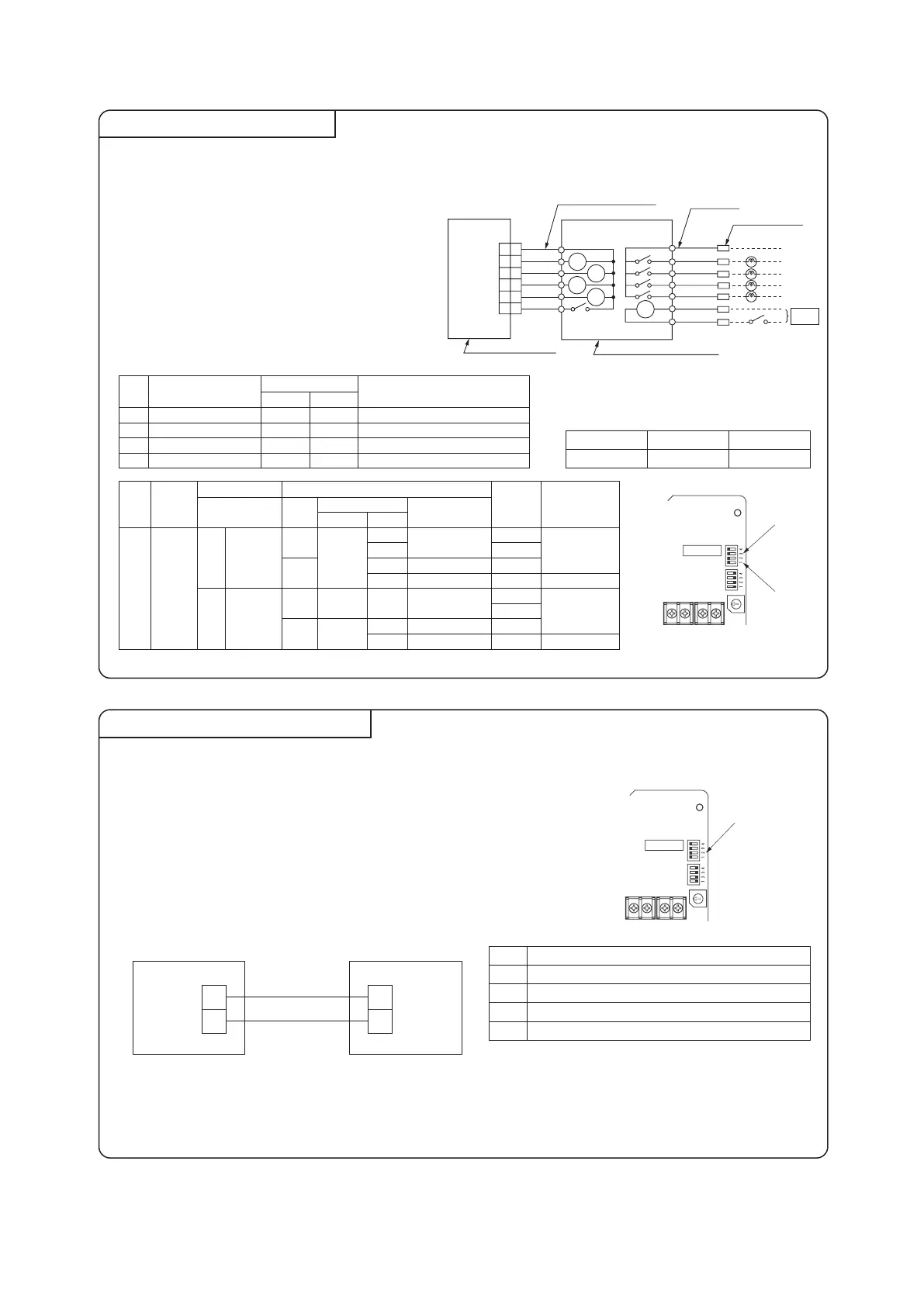
It is available to operate the air-conditioning unit and to monitor the operation status with the external control unit (remote display)
by sending the input/output signal through CnT connector on the indoor control PCB.
①Connect a external remote control unit (procured locally)
to CnT terminal.
②In case of the pulse input, switch OFF the DIP switch
SW2-1 on the interface PCB.
③When setting operation permission/prohibition mode,
switch OFF the DIP switch SW2-3 on the interface PCB.
Connection of Superlink E board
Functions of CnT connector
①Switch ON the DIP switch SW2-2 (Factory setting: ON) on the interface PCB.
②Wiring connection between the interface and the Superlink E board.
③Clamp the connection cables with cable clamps.
Regarding the connection of Superlink E board, refer to the instruction manual of Superlink E board.
For electrical work, power source for all of units in the Superlink system
must be turned OFF.
Caution:Wireless remote control attached to the indoor unit can be used in parallel, after
connecting the wired remote control. However, some of functions other than
the basic functions such as RUN/STOP, Temperature Setting, etc. may not work
properly and may have a mismatch between the display and the actual behavior.
No.
1
2
3
4
Within 200 m 0.5 mm
2
× 2 cores
Within 300 m 0.75 mm
2
× 2 cores
Within 400 m 1.25 mm
2
× 2 cores
Within 600 m 2.0 mm
2
× 2 cores
* Factory setting
Interface side Superlink E board
Indoor units
control box
Do not use the length over 2 meter
CnT
(Blue 6P)
Common
Output 1
Output 2
Output 3
Output 4
Remote start / stop button or timer point
Butt splice
(Application coverage
0.75-1.25mm
2
)
Remote start/stop kit (procured locally)
0.75mm
2
×2m
Note (1) 0.3mm
2
×2m
Red
Black
Yellow
Blue
Brown
Orange
White
Black
Yellow
Blue
Brown
Orange
Orange
Input
power
+12
PCB (Printed Circuit Board)
XR1
XR1
XR2
XR3
XR4
XR2
XR3
XR4
XR5
XR5
11
22
33
44
55
66
 Loading...