-
18
-
'12 • SRK-T-130
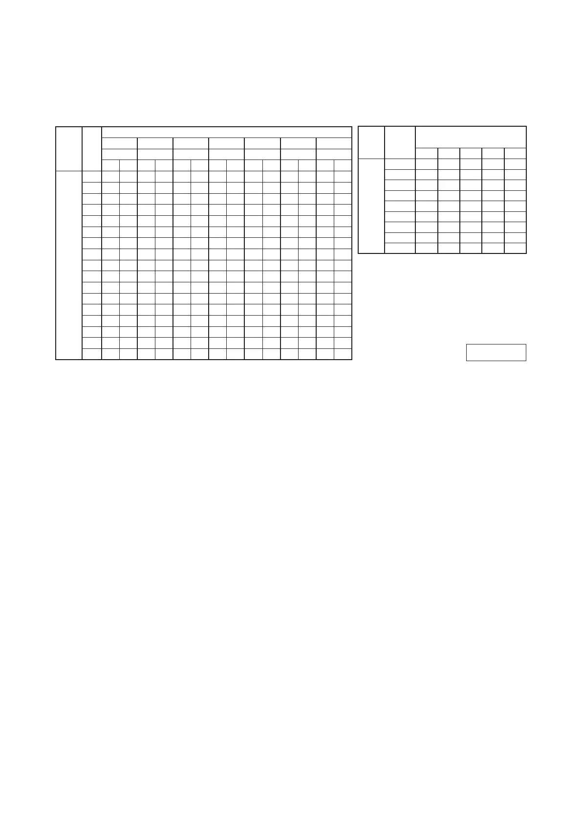
7. CAPACITY TABLE
ISC12091
Model
SRK92ZL-S Cool Mode
Heat Mode(HC)
Air flow
Outdoor
air temp.
Indoor air temp
21
℃
DB 23
℃
DB 26
℃
DB 27
℃
DB 28
℃
DB 31
℃
DB 33
℃
DB
14
℃
WB 16
℃
WB 18
℃
WB 19
℃
WB 20
℃
WB 22
℃
WB 24
℃
WB
TC SHC TC SHC TC SHC TC SHC TC SHC TC SHC TC SHC
Hi
21.0
(m
3
/min)
10
10.37
7.61
10.85
7.48
11.25
7.67
11.44
7.56
11.64
7.44
11.98
7.58
12.30
7.31
12
10.18
7.51
10.67
7.38
11.09
7.59
11.29
7.48
11.49
7.38
11.85
7.52
12.18
7.27
14 9.99 7.40
10.48
7.28
10.93
7.51
11.13
7.41
11.34
7.31
11.72
7.47
12.06
7.23
16 9.79 7.28
10.29
7.19
10.76
7.43
10.98
7.34
11.18
7.25
11.58
7.41
11.93
7.18
18 9.59 7.18
10.09
7.07
10.58
7.34
10.81
7.26
11.02
7.17
11.43
7.36
11.79
7.13
20 9.38 7.06 9.88 6.98
10.40
7.26
10.64
7.19
10.85
7.09
11.28
7.29
11.65
7.07
22 9.16 6.96 9.67 6.87
10.21
7.17
10.47
7.11
10.68
7.00
11.13
7.24
11.50
7.02
24 8.94 6.84 9.45 6.77
10.02
7.07
10.29
7.01
10.50
6.93
10.97
7.17
11.35
6.97
26 8.72 6.72 9.22 6.65 9.82 6.98
10.10
6.94
10.32
6.86
10.80
7.11
11.19
6.89
28 8.49 6.59 8.99 6.54 9.62 6.90 9.91 6.86
10.13
6.78
10.63
7.01
11.03
6.83
30 8.25 6.48 8.76 6.42 9.41 6.80 9.71 6.78 9.93 6.71
10.45
6.95
10.86
6.78
32 8.01 6.35 8.51 6.31 9.20 6.71 9.51 6.69 9.73 6.62
10.27
6.88
10.68
6.72
34 7.77 6.23 8.27 6.19 8.98 6.61 9.31 6.59 9.52 6.53
10.08
6.82
10.50
6.66
35 7.64 6.17 8.14 6.13 8.86 6.56 9.20 6.55 9.42 6.49 9.99 6.78
10.41
6.63
36 7.51 6.11 8.01 6.07 8.75 6.50 9.09 6.51 9.31 6.45 9.89 6.75
10.32
6.60
38 7.26 5.97 7.75 5.94 8.52 6.41 8.88 6.41 9.09 6.35 9.69 6.68
10.12
6.53
39 7.12 5.91 7.62 5.88 8.40 6.35 8.77 6.37 8.98 6.31 9.59 6.63
10.03
6.50
(
kW
)
Air flow
Outdoor
air temp.
Indoor air temp
16
℃
DB 18
℃
DB 20
℃
DB 22
℃
DB 24
℃
DB
Hi
23.5
(m
3
/min)
-15
℃
WB 6.15 6.02 5.88 5.76 5.63
-10
℃
WB 6.96 6.84 6.75 6.58 6.44
-5
℃
WB 7.54 7.43 7.28 7.20 7.08
0
℃
WB 7.91 7.79 7.65 7.56 7.45
5
℃
WB 10.07 9.95 9.90 9.70 9.57
6
℃
WB 10.23 10.11 10.00 9.87 9.75
10
℃
WB 10.87 10.77 10.70 10.56 10.45
15
℃
WB 11.84 11.73 11.65 11.52 11.41
20
℃
WB 12.72 12.62 12.56 12.41 12.31
Note (1) These data show average statuses.
Depending on the system control, there may be ranges where the operation is not conducted continuously.
These data show the case where the operation frequency of a compressor is xed.
(2) Capacities are based on the following conditions.
Corresponding refrigerant piping length : 7m.
Level difference of Zero.
(3) Symbols are as follows.
TC:Total cooling capatity
SHC:Sensible heat capacity
HC:Heating capacity
(
kW
)
 Loading...