L1
L3
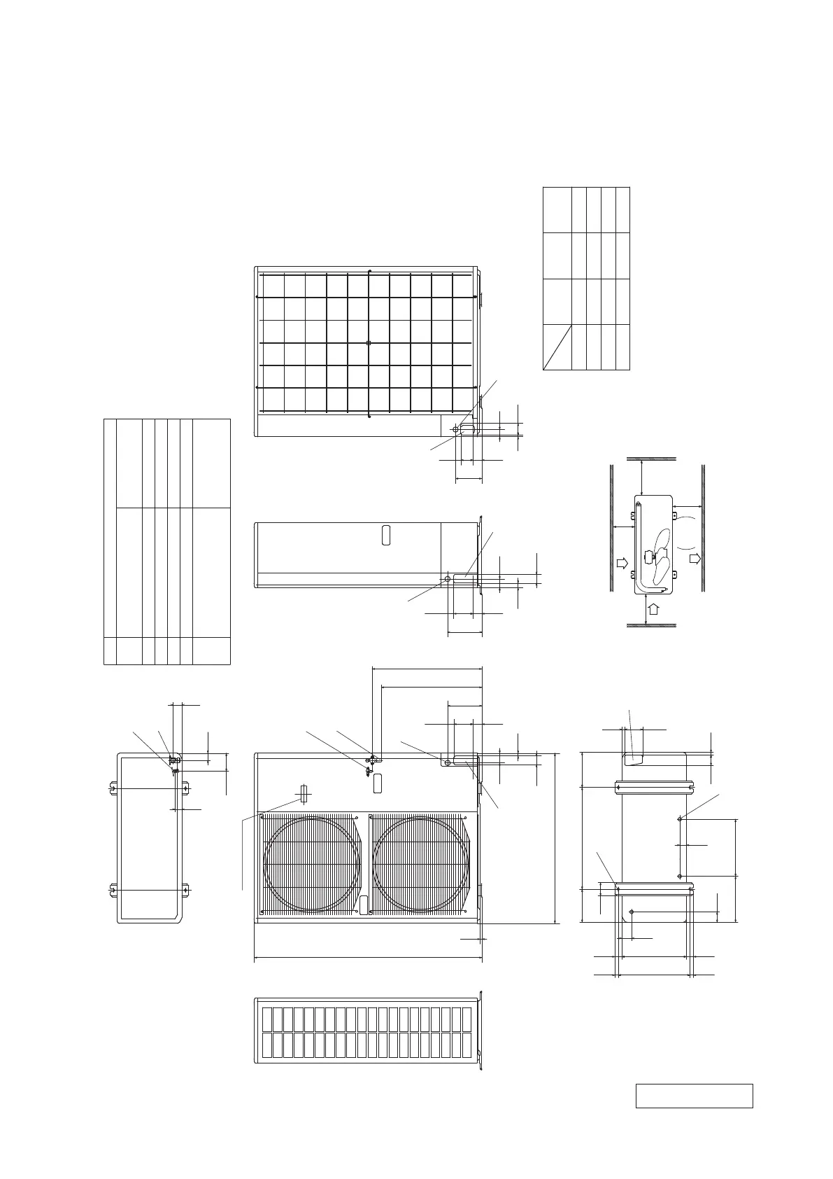
Intake
L2
Intake
Outlet
L4
space
Service
B
A
E
C
D
F
C
C
F
C
F
B
A
Minimum installation space
φ
15.88(5/8")(Flare)
Content
C Pipe/cable draw-out hole
D
E Anchor bolt hole
Drain discharge hole
Symbol
B
A
M10
×
4places
φ20×3places
Service valve connection(liquid side)
φ
6.35(1/4")(Flare)
Unit:mm
Service valve connection of the
attached connecting pipe(gas side)
41
51
40
103
60
262 325
38
15
60
15
103
200580190
55
40370
40
41020 20
76
L2
L3
L4
L1
300
100
250
Open
Open
250
100
500
Open
250
150
250
Examples of
Dimensions
installation
The height of a wall is 1200mm or less
Terminal block
67
9
150
7050
195
11050
50
27
50
1300
10
970
55
15
50
195
11050
41
F Cable draw-out hole
φ30(front)
φ45(side)
φ50(back)
626
574
Ⅰ Ⅱ
Ⅲ
Notes
(1) It must not be surrounded by walls on the four sides.
(2) The unit must be fixed with anchor bolts. An anchor bolt must not
protrude more than 15mm.
(3) Where the unit is subject to strong winds, lay it in such
a direction that the blower outlet faces perpendicularly
to the dominant wind direction.
(4) Leave 1m or more space above the unit.
(5) A wall in front of the blower outlet must not exceed the units height.
(6) The model name label is attached on the rear panel.
 Loading...