– 27 –
Installation of indoor unit
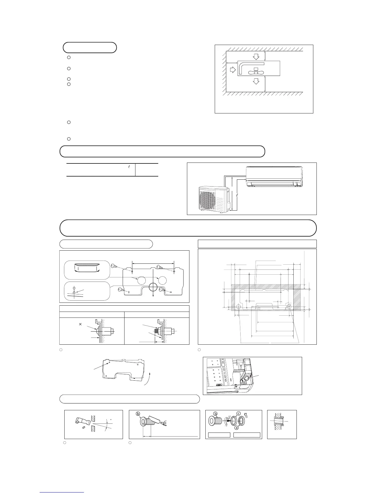
Limitations for one way piping length and vertical height difference
Total one way piping length ( ) Max. 15 m
Vertical height difference (h) Max. 10 m
h
A place where good air circulation can be obtained and where rain,
snow or sunshine will not directly strike the unit.
A place where discharged hot air or unit’s operating sound will not
be a nuisance to the neighborhood.
A place where servicing space can be secured.
A place where vibration will not be enlarged.
*Avoid installing in the following places.
•A place near the bedroom and the like, so that the operation
noise will cause no trouble.
•
A place where there is possibility of flammable gas leakage.
•A place exposed to strong wind.
•In a salt-laden atmosphere or a place where the generation of oil mist, vapor or fume is expected.
Blowing out port and suction port on the back side of the unit can be installed at a distance of 10cm from walls.
In case the barrier is 1.2m or above in height, or is overhead, the
sufficient space between the unit and wall shall be secured.
When the unit is installed, the space of the following dimension and above shall be secured.
OUTDOOR UNIT
60 cm MIN
Air intake
10 cm MIN
10 cm
MIN
Air outlet
Air
intake
No obstacles
(Service space
for electrical
parts)
Note (1) If the wall is higher than 1.2 m or a ceiling
is present, distances larger than indicated
in the above table must be provided.
( )
Look for the inside wall structures (Intersediats support or pillar and finally install
the unit after level surface has been checked.)
450
Level position (2 locations)
Mating mark for
level surface
Fixing on concrete wall
Use of nut anchor Use of bolt anchor
Nut
(M6)
Mounting
board
Mounting
board
Max.10
Bolt
(M6 12)
INSTALLATION SPACE (INDOOR UNIT)
(FRONT VIEW)
50
Space for
service
Space for
service
120
220
650
450 220
100
120
35
35
58
54
520.8
491.1
559.1
49222.5
48
100 Space for service 15 Space for service
7.7295.75.6
48
Indoor unit
Installation board
Drain hose (ø16)
Piping for Gas
Piping for Liquid
Piping hole (ø65)
Piping hole (ø65)
Relation between setting plate and indoor unit
Piping for Liquid : ø6.35
Piping for Gas : ø12.7
Installation of Installation plate
Standard hole
Nothing is connected to
this hole on the back of
indoor unit.
Adjustment of the installation plate in the horizontal direction is to be conducted
with four screws in a temporary tightened state.
Adjust so the plate will be level by turning the board with the standard hole
as the center.
Drill a hole with whole core drill. In case of rear piping draw out, cut off the lower
and the right side portions of the sleeve collar.
When drilling the wall that contains a metal lath, wire lath or metal plate, be sure to use pipe hole sleeve sold separately.
Drilling of holes and fixture of sleeve (Option parts)
Top
Indoor side
Outdoor side
Thicknese of the wall + 1.5cm
5
65
Indoor side Outdoor side Installed state
Turn to
tighten
 Loading...