Lid
Te
rminal cover
The screw of the lid
is tightened securely.
○Perform wiring, please take care of connecting the
terminal number of outdoor unit terminal block.
Terminal block
Clamp
Screw
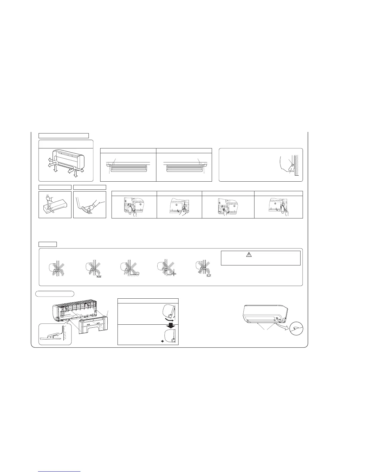
Fixing of installation board
Relation between setting plate and indoor unit
Drill a hole with whole core drill.
Thickness of the wall +1.5 cm
In case of rear piping draw out, cut off the lower
and the right side portions of the sleeve collar.
5
°
○
○
ø65
INSTALLATION OF INDOOR UNIT
Installation of Installation board
Drilling of holes and fixture of sleeve (Option parts)
Installed state
Top
●
Matters of special notice when piping from left or central/rear of the unit.
[Top view]
Left-hand-sided piping
Piping in the left rear direction
Piping in the left direction
Piping in the right direction
Piping in the right rear direction
Higher than specified
Wavy
Right
Rear
Downward
Left rear
Left
Left downward
Right-hand-sided piping
Look for the inside wall structures (Intermediate support or pillar
and firmly install the unit after level surface has been checked.)
Mating mark for
level surface
Level position (2 locations)
Gutter
Pipe accommodating section
Since this air conditioner has
been designed to collect dew
drops on the rear surface to
the drain pan, do not attach
the power cord above the
gutter.
RLC012A001A
When drilling the wall that contains a metal lath, wire lath or metal plate, be sure to use pipe hole sleeve sold separately.
Standard hole
○Adjustment of the installation board in the horizontal
direction is to be conducted with four screws in a
temporary tightened state.
○Adjust so the board will be level by turning the
board with the standard hole as the center.
Indoor side Outdoor side
394
The gap to the ground is
5 cm or less.
The drain hose tip is
in the gutter.
The drain hosetip is
in water.
Shaping of pipings
Taping of the exterior
Piping
Drain hose
Installing the support of piping
Drainage
○Hold the bottom of the
piping and fix direction
before stretching it and
shaping it.
○Tape only the portion that
goes through the wall.
○Always tape the wiring
with the piping.
Sufficient care must be taken not to damage the panel
when connecting pipes.
Fixing of indoor unit
Indoor unit
Installation board
W
all
Indoor unit base lower latch
L
a
t
ch
(
2
loca
t
i
on
s)
Installation
board
Installation Steps
①Pass the pipe through the hole
in the wall, and hook the upper
part of the indoor unit to the
installation board.
②Gently push the lower part to
secure the unit.
Odor from
the gutter
Indoor side
Outdoor side
Turn to
tighten
Putty
[Drain hose changing procedures]
1. Remove the drain hose. 2. Remove the drain cap.
○Remove it with hand or pliers.○Remove the screw and drain hose,
making it rotate.
.eso
hnia
r
dehttc
ennoC
.4
.
pacnia
r
deht
t
resnI
.3
○Insert the drain cap which was removed
at procedure “2” securely using a
hexagonal wrench etc.
Note: Be careful that If it is not inserted
securely, water leakage may occur.
○Insert the drain hose securely, making
rotate. And install the screw.
Note: Be careful that If it is not inserted
securely, water leakage may
occur.
●
How to remove the indoor unit from the installation board
The marked portion of the indoor
unit base lower latch
①Push up at the marked portion of
the indoor unit base lower latch,
and slightly pull it toward you.
(both right and left hand sides)
(The indoor unit base lower latch
can be removed from the
installation board)
②Push up the indoor unit upward.
So the indoor unit will be removed
from the installation board.
Piping is possible in the rear, left, left rear,
left downward, right or downward direction.
○P
our water to the drain pan located under the heat exchanger,
and ensure that the water is discharged outdoor.
○When the extended drain hose is indoor, securely insulate it
with a heat insulator available in the market.
○Arrange the drain hose in a downward angle.
○Avoid the following drain piping.
Go through all installation steps and check if the drainage is
all right. Otherwise, water leak may occur.
CAUTION
Clearance
○Remove the flared nuts.
(on both liquid and gas sides)
○Remove the flared nuts.
(on both liquid and gas sides)
○Install the removed flared nuts to the pipes to be connected,
then flare the pipes.
roodt
u
OroodnI
Press
Remove
Press
Remove
A
90±0.5°
Dimension A
Liquid side : 9.1
Gas side Model SRK25/35,
DXK09/12 : 13.2
Model SRK45,
DXK15 : 16.6
CONNECTION OF REFRIGERANT PIPINGS
Keep the openings of the pipes covered with tapes etc. to prevent dust, sand, etc. from entering them.
(Do not turn)
○Connect the pipes on both liquid and gas sides.
○Tighten the nuts to the following torque.
Liquid side(
φ
6.35) : 14.0 ~ 18.0 N・m (1.4~1.8 kgf
・m)
Gas side (
φ
9.52) : 34.0 ~ 42.0 N・m (3.4~4.2 kgf
・m)
(
φ
12.7) : 49.0 ~ 61.0 N・m (4.9~6.1 kgf
・m)
Indoor
Liquid side
Gas side
Outdoor
Liquid side
Gas side
(Do not turn)
INSTALLATION OF THE OUTDOOR UNIT
The power supply voltage is correct as the rating.
No gas leaks from the joints of the operation valve.
Pow
er cables and crossover wires are securely fixed
to the terminal board.
Operation valve is fully open.
The pipe joints for indoor and outdoor pipes have been insulated.
The screw of the lid is tightened securely.
The screw of the service panel is tightened securely.
Use a flare tool designed for R410A or a conventional flare
tool. Please note that measurement B (protrusion from the
flaring block) will vary depending on the type of a flare tool in
use. If a conventional flare tool is used, please use a copper
pipe gauge or a similar instrument to check protrusion so
that you can keep measurement B to a correct value.
Copper pipe
diameter
Clutch type flare tool
for R410A
Conventional (R22) flare tool
Clutch type Wing nut type
Measurement B (mm)
6.35
9.52
12.7
0.0~ 0.5
0.0~ 0.5
0.0~ 0.5
1.0~ 1.5
1.0~ 1.5
1.0~ 1.5
1.5~ 2.0
1.5~ 2.0
2.0~ 2.5
Measurement B
Flaring block
Copper pipe
Connection
Preparation
Drain piping work
Fixing of outdoor
● Flaring work
○Make sure that the unit is stable in installation.
Fix the unit to stable base.
○When installing the unit at a higher place or where
it could be toppled by strong winds, secure the unit
firmly with foundation bolts, wire, etc.
○Execute drain piping by using a drain elbow and drain grommets supplied
separately as accessories, where water drained from the outdoor unit is a
problem.
○Water may drip where there is a larger amount of drain water. Seal around
the drain elbow and drain grommets with putty or adequate caulking
material.
○Condensed water may flow out from vicinity of operation valve or
connected pipes.
○Where you are likely to have several days of sub-zero temperatures in a
row, do not use a drain elbow and drain grommets. (There is a risk of
drain water freezing inside and blocking the drain.)
Electric wiring work
○Perform wiring, making wire terminal numbers
conform to terminal numbers of indoor unit terminal
block.
○Connect using ground screw located near mark.
Do not apply excess torque to the flared nuts.
Otherwise, the flared nuts may crack depending on the
conditions and refrigerant leak may occur.
CAUTION
Do not apply refrigerating machine oil to the flared surface.
CAUTION
Air purge
Insulation of the connection portion
Finishing work and fixing
①Tighten all flare nuts in the pipings both indoor and
outside wall so as not to cause leak.
②Connect operation valve, charge hose, manifold valve
and vacuum pump as is illustrated right.
③Open manifold valve handle Lo to its full width, and
perform vacuum or evacuation.
Continue the vacuum or evacuation operation for 15
minutes or more and check to see that the vacuum
gauge reads -0.1MPa.
④After completing vacuum operation, close the Lo
handle and stop operation of the vacuum pump.
⑤
After completing vacuum operation, fully open
operation valve (Both gas and liquid sides) with
hexagon headed wrench.
⑥
Check for possible leakage of gas in the connection
parts of both indoor and outdoor.
●Since the system uses check joints differing in diameter from those found on the conventional models, a charge hose
(for R22) presently in use is not applicable. Please use one designed specifically for R410A.
●Please use an anti-reverse flow type vacuum pump adapter so as to prevent vacuum pump oil from running back
into the system. Oil running back into an air-conditioning system may cause the refrigerant cycle to break down.
Cover the exterior portion
with outer tape and shape
the piping so it will match
the contours of the route
that the piping to take.
Also fix the wiring and
pipings to the wall with
clamps.
Refrigerant piping
Connection wiring,
Earth wiring
Outer tape
Clamp
Wood screw
Drain hose
Cover the coupling with insulator and then cover it with
tape.
Vinyl tape
Place the slit
upward.
(three-way valve)
Charge hose (Designed specifically for R410A)
Compound pressure gauge
Pressure gauge
Gauge manifold
(Designed specifically for R410A)
Handle Hi
Vacuum pump
Vacuum pump adapter
(Anti-reverse flow type)
(Designed specifically for R410A)
Charge hose
(Designed specifically for R410A)
Check joint
-0.1MPa
(-76cmHg)
Handle Lo
Operation valve
Operation valve
(two-way valve)
Operation valve
cap
Operation valve
cap
Operation valve cap
tightening torque (N·m)
Check joint blind nut
tightening torque ( )
φ6.35 (1/4")
φ 01
)
"8/3(
2
5.9 〜12
φ12.7 (1/2") 25〜35
20
〜30
Operation valve size
(mm)
Securely tighten the operation valve cap and the check joint blind nut after adjustment.
○When condensed water needs to be led to a drain, etc., install the unit on
a flat base (supplied separately as an option part) or concrete blocks.
Then, please secure space for the drain elbow and the drain hose.
INSTALLATION TEST CHECK POINTS
After installation
Check the following points again after completion of the installation, and before turning on the power. Conduct a test run again and ensure that the unit operates properly.
At the same time, explain to the customer how to use the unit and how to take care of the unit following the instruction manual.
Test run
Air conditioning operation is normal.
No abnormal noise.
Water drains smoothly.
Protective functions are not working.
The remote control is normal.
(Three-minute restart preventive timer)
When the air conditioner is restarted or when changing the
operation, the unit will not start operating for approximately
3 minutes. This is to protect the unit and it is not a malfunction.
Operation of the unit has been explained to the customer.
(
Unit : mm
)
⑧ Drain elbow
⑦ Grommet
Drain hose
(To be procured on the installer’s part)
Do not put a grommet on this hole.
This is a supplementary drain hole
to discharge drain water, when a
large quantity of it is gathered.
CAUTION
Interconnecting and
grounding wires
(minimum)
SRK25 / DXK09
SRK35 / DXK12
SRK45 / DXK15
Switch breaker
Over current protector
rated capacity
Power source
(minimum)
Model
15A, 30mA,
0.1sec or less
30A 16A 2.0mm
2
1.5mm
2
X 4
Earth leakage
breaker
Phase
Single
-phase
○Always perform grounding system installation work with the power cord unplugged.
○Connect a pair bearing a common terminal number with an indoor-outdoor connecting wire.
○
In cabling, fasten cables securely with cable clamps so that no external force may work on terminal connections.
○Grounding terminals are provided in the control box.
Always use an earth leakage circuit breaker designed for inverter circuits
to prevent a faulty operation.
○The specifications shown in the above table are for units without heaters. For units with heaters, refer to the
installation instructions or the construction instructions of the indoor unit.
○Switchgear or Circuit breaker capacity which is calculated from MAX. over current should be chosen along the
regulations in each country.
○The cable specifications are based on the assumption that a metal or plastic conduit is used with no more than
three cables contained in a conduit and a voltage drop is 2%. For an installation falling outside of these conditions,
please follow the internal cabling regulations. Adapt it to the regulation in effect in each country.
Switchgear or Circuit Breaker
CAUTION
power cable, indoor - outdoor connecting wire circuit diagram
Indoor - Outdoor
connecting wire
Please connect the
earthed line of indoor
and outdoor connect-
ing wire to a bracket
part of the illustration.
CAUTION
Power cable
INSTALLATION SPACE (INDOOR UNIT) (FRONT VIEW)
(
Unit : mm
)
Piping for Liquid Model SRK25~45, DXK09~15 :
ø
6.35
Piping for Gas Model SRK25/35, DXK09/12 :
ø
9.52
Model SRK45, DXK15 :
ø
12.7
190 40.1
47
130.5 508 130.5
157 455
157
187.5
394
187.5
47
7.6247.56.9
65
Space
50
service
100
55
Piping for Gas 359.5
Piping for Liquid 427.5
Drain hose 530 (ø16)
55
Installation board
indoor unitSpace for
service
Space for
for service
15 Space
for service
Piping hole (ø65)
Piping hole (ø65)
Preparation of indoor unit
Mounting of connecting wires
① Remove the lid.
②
Remove the terminal cover.
③ Remove the wiring clamp.
④ Connect the connecting wire securely to the terminal block.
1) Connect the connection wire securely to the terminal block. If
the wire is not affixed completely, contact will be poor, and it is
dangerous as the terminal block may heat up and catch fire.
2) Take care not to confuse the terminal numbers for indoor and
outdoor connections.
⑤ Fix the connecting wire by wiring clamp.
⑥ Attach the terminal cover.
⑦ Attach the lid.
Use cables for interconnection wiring to avoid loosening of the
wires. CENELEC code for cables Required field cables.
In case of faulty wiring connection, the indoor unit stops,
and then the run lamp turns on and the timer lamp blinks.
H
05
R
N
R
4
or
5
G
1.5
H05RNR4G1.5 (Example) or 245ICE57
Harmonized cable type
300/500 volts
Natural-and/or synch. rubber wire insulation
Polychloroprene rubber conductors insulation
Stranded core
Number of conductors
One conductor of the cable is the earth conductor
(yellow/green)
Section of copper wire (mm
2
)
CAUTION
 Loading...