( )
D
E
B
A
C
50
322
135
275
120.5
74.5 480 90.5 20.2
645 57.2
14.8
336
16.8
304.4
12
40
16.5
540
86.3
43.2
147.2
Center of gravity
※3
※1
※2
φ9.52(3/8")(Flare)
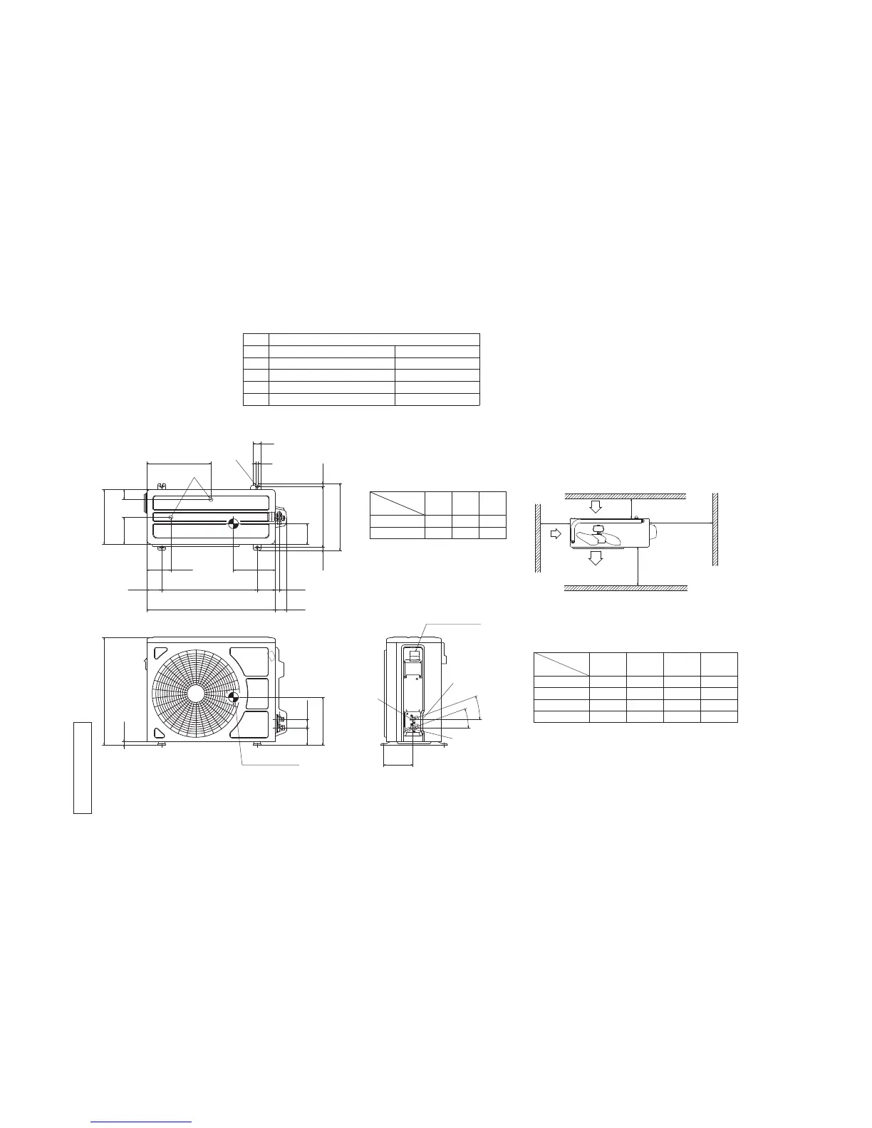
Content
C Pipe/cable draw-out hole
D
E Anchor bolt hole
Drain discharge hole
Symbol
B
A Service valve connection(gas side)
M10×4places
φ20×2places
Service valve connection(liquid side)
φ6.35(1/4")(Flare)
Unit:mm
L2
Intake
Outlet
Intake
L3
L1
Minimum installation space
Service
space
L4
L2
L3
L4
L1
100
100
250
Open
I Ⅱ Ⅲ Ⅳ
Open
250
80
280
280
Open
80
100
Examples of
Dimensions
installation
180
Open
80
Open
Terminal block
SRC35ZMP-S
SRC25ZMP-S
220
210
※1
108
103240
240
Dimensions
MODEL
※2 ※3
2
0
゜
2
0
゜
Notes
(1) It must not be surrounded by walls on the four sides.
(2) The unit must be fixed with anchor bolts. An anchor bolt must not
protrude more than 15mm.
(3) Where the unit is subject to strong w inds, lay it in such
a direction that the blower outlet faces perpendicularly
to the dominant wind direction.
(4) Leave 1m or more space above the unit.
(5) A wall in front of the blower o utlet must not exceed the units height.
(6) The model name label is attached on the right side of the unit.
 Loading...