www.mo-sys.com
4
System Overview
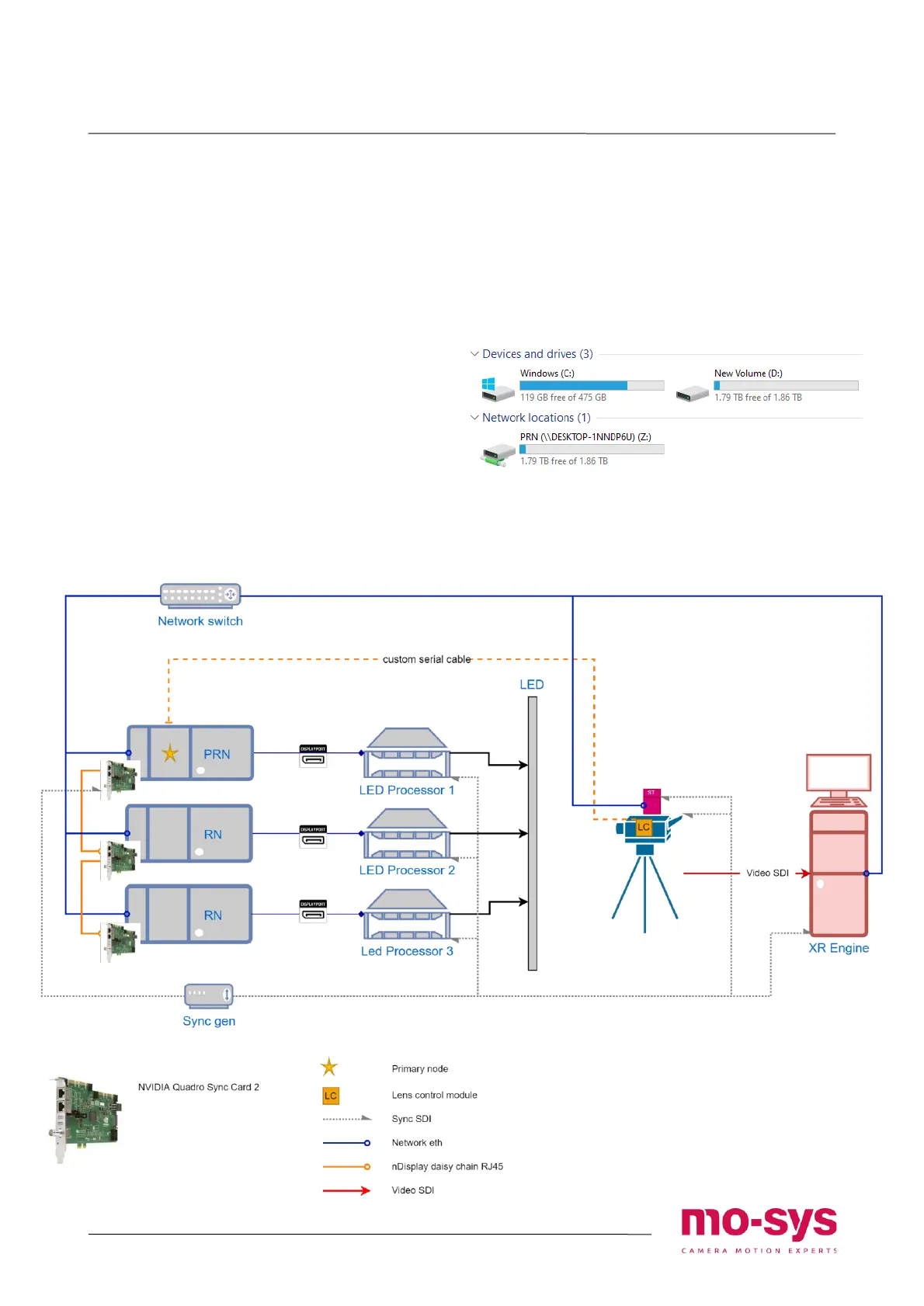
Connections diagram
The diagram below represents a setup with
three Render Nodes (RN) corresponding to
the LED processors.
Notes:
1. Set StarTracker only to send data to XR
Engine and Primary Render Node (PRN).
Tracking is passed automatically on
other Render Nodes. The tracking won’t
be just passed through Unreal’s Multi-
user if using in a configuration with a
dedicated editor computer.
2. The network is solely used for tracking
updates, triggering nDisplay and events.
There is no image streaming over
network.
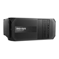
Network drives
Render nodes are mapped as network
drives on XR Engine, so it’s easier to
distribute the project across.
Normally most of the editing can be done
on XR Engine and just copied to the
rendering nodes.
Drives visible from XR Engine