30
GAS-FIRED BOILER Boiler Manual
PART 6: VENTING, COMBUSTION AIR & CONDENSATE REMOVAL (CONTINUED)
E. EXHAUST VENT AND INTAKE AIR VENT
SIZING
1. The exhaust vent and intake air vent pipes
are 4" for the Mod Con 300 and 500, and 6"
for the Mod Con 850.
2. The total combined equivalent length of
exhaust vent and intake air pipe should not
exceed 200 feet.
a. The equivalent length of elbows, tees,
and other fittings are listed in the Friction
Loss Table 6-8.
*Friction loss for long radius elbow is 1 foot less.
b. For example: If the exhaust vent has two
short 90° elbows and 10 feet of PVC pipe
we will calculate:
Exhaust Vent Pipe Equivalent Length = (2x3)+10=16 feet
Further, if the intake air vent pipe has two
90° elbows, one 45° elbow and 10 feet of
PVC pipe, the following calculation
applies:
Intake Air Vent Pipe Equivalent Length = (2x3)+1+10=17 feet
c. The intake air vent pipe and the exhaust
vent are intended to penetrate the same
wall or roof of the building.
d. Effort should be made to keep a
minimum difference in equivalent length
between the intake air vent pipe and the
exhaust vent.
3. The minimum combined equivalent length is
15 equivalent feet.
F. LONGER VENT RUNS
1. The maximum combined equivalent length
can be extended by increasing the diameter
of both exhaust vent and intake air vent pipe
equally. However, the transitions should
begin a minimum of 15 equivalent feet from
the boiler on both the intake and exhaust
equally.
a. The maximum equivalent length for the
increased diameter vent pipes is 275 feet,
which includes the combined 30 feet from
the boiler, 15 ft. (inlet) + 15 ft. (exhaust) =
30 ft. combined with transition total of 245
ft. upsize piping for longer vent runs.
b. Transitions must always be made in
vertical sections of pipe to prevent the
condensate from pooling in the vent
pipe.
c. If the transition occurs at a distance
greater than 15 equivalent feet from the
boiler, the maximum equivalent length
will be reduced.
G. EXHAUST VENT AND INTAKE AIR PIPE
INSTALLATION
1. Use only solid PVC, or CPVC schedule 40 or
80 pipe and AL294C Stainless Steel. FOAM
CORE PIPING IS ONLY ALLOWED FOR
INTAKE PIPING.
2. Remove all burrs and debris from joints and
fittings.
3. All joints must be properly cleaned, primed,
and cemented. Use only cement and primer
approved for use with the pipe material.
Refer to the Venting Table 6-4.
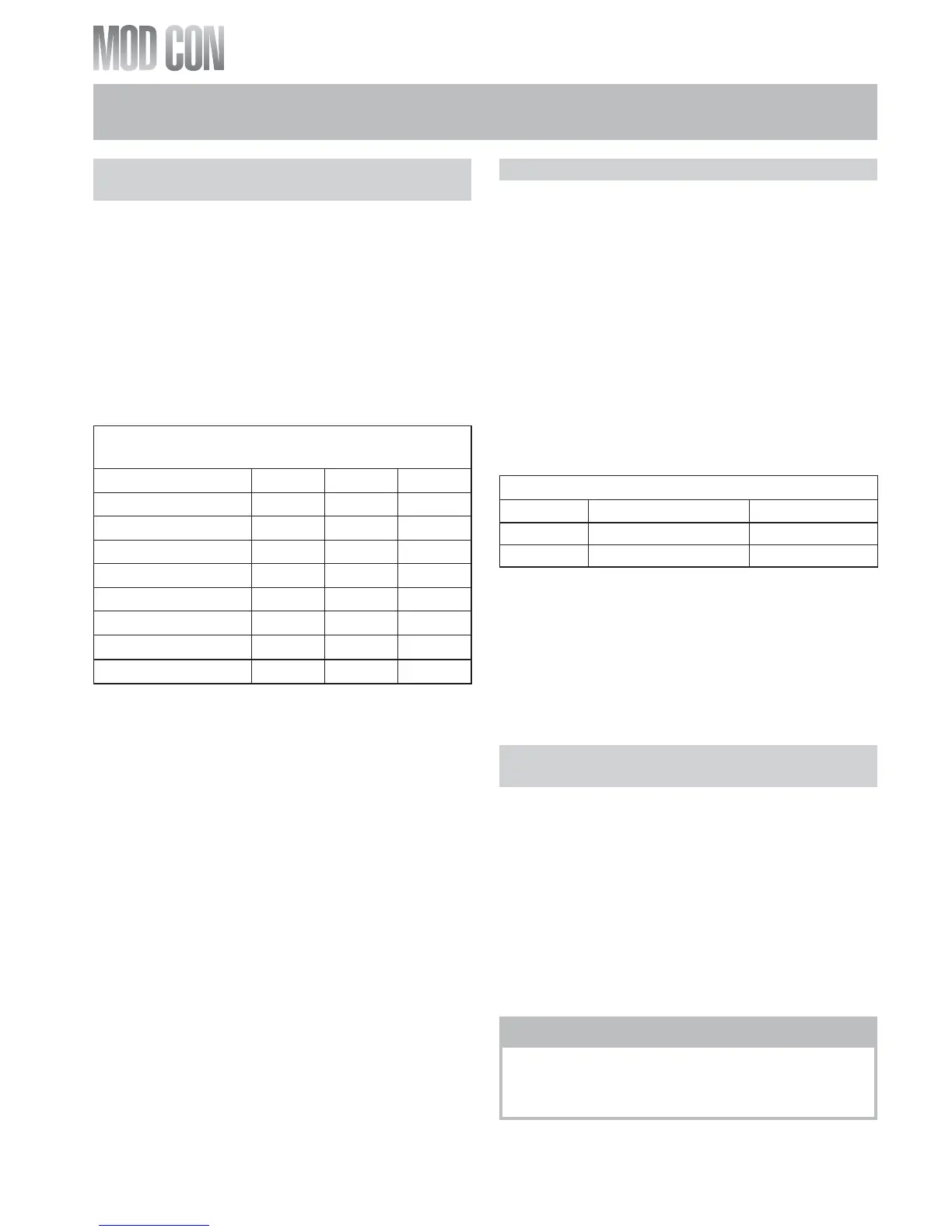
Friction Loss Equivalent for
Stainless or Plastic Piping and Fittings
Fitting Description 4" 6" 8"
90° elbow short radius 3' 3' 3'
90° elbow long radius 2' 2' 2'
45° elbow 1' 1' 1'
Coupling 0' 0' 0'
Tee (intake only) 0' 0' 0'
V Series Vent Kit 1' 1' 1'
AL29 4C Vent Terminal 1' 1' 1'
Pipe (All materials) 1’ 1’ 1’
Table 6-8
Vent Transition Fitting
Size Reducing Coupling Final Vent Size
4" venting 6" x 4" 6"
6" venting 8" x 6" 8"
Table 6-9
n
WARNING
All joints of positive pressure vent systems
must be sealed completely to prevent leakage
of flue products into the living space.