32
GAS-FIRED BOILER Boiler Manual
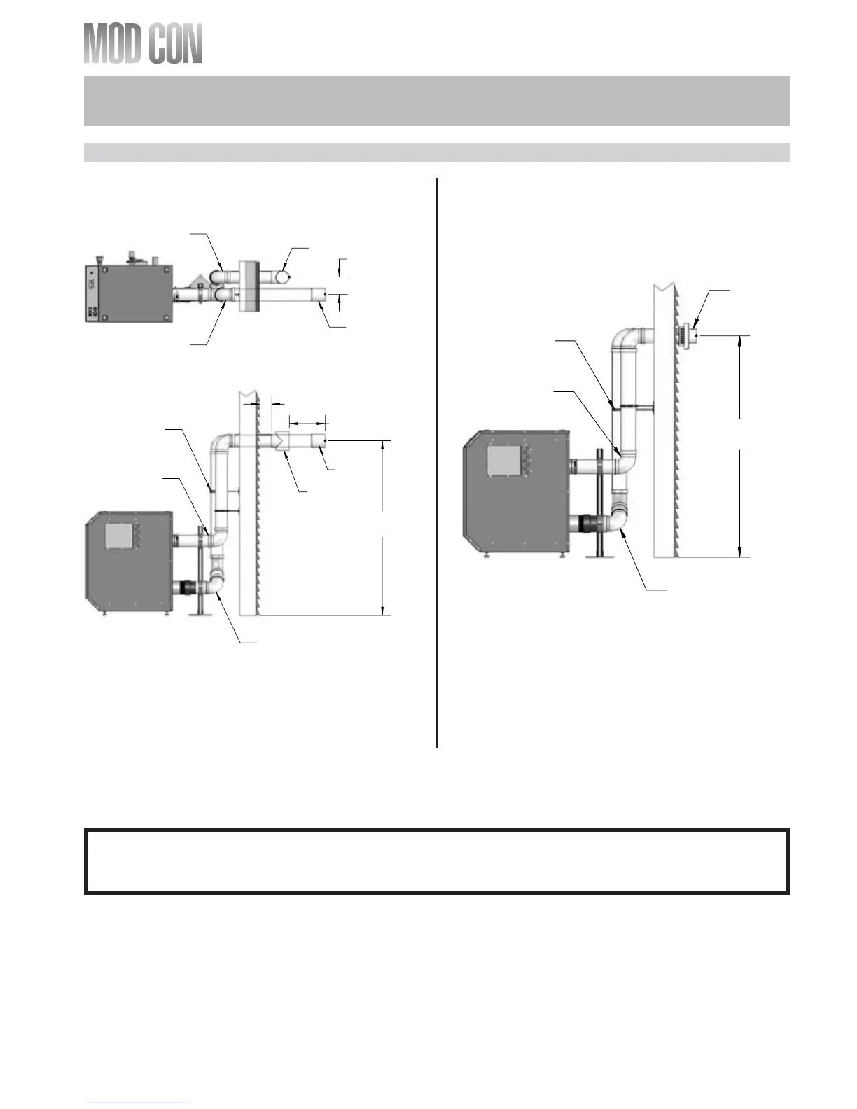
I. DIAGRAMS FOR SIDEWALL VENTING
GENERAL NOTE: All vent pipes must be glued, properly supported and the exhaust must be pitched a
minimum of a ¼" per foot back to the heater (to allow drainage of condensate).
0,1
0,1
327(17,$/612:/(9(/
25
$%29(0$;
5,*+76,'(9,(:
(;+$867
9(17
$,5,17$.(
9(17
6833257%5$&.(76
0867%(86('21
$//+25,=217$/
$1'9(57,&$/3,3,1*
7((
675$,*+7
&283/,1*
7239,(:
0$;
(;+$867
9(17
$,5,17$.(
9(17
7((
675$,*+7
&283/,1*
127(9(170867%($7/($6729(50$;,080612:
/(9(/25:+,&+(9(5,6*5($7(5&+(&.:,7+/2&$/
&2'(5(48,5(0(176
NOTE: When placing support brackets on vent piping, the first bracket must be within 1 foot of the
appliance and the balance at 4 foot invervals on the vent pipe. The boiler venting must be readily
accessible for visual inspection for the first three feet from the boiler.
Figure 6-9
LP-205-E Rev. 5/15/08 Figure 6-10 LP-205-F Rev. 5/15/08
SIDEWALL VENTING W/TEE (INTAKE)
AND COUPLING (EXHAUST)
327(17,$/612:/(9(
25
$%29(0$;
5,*+76,'(9,(:
6833257%5$&.(76
0867%(86('21
$//+25,=217$/
$1'9(57,&$/3,3,1*
(;+$867
9(17
,17$.($,5
9(17
9(17.,7
6((&+$57
127(9(170867%($7/($6729(50$;,080612:
/(9(/25:+,&+(9(5,6*5($7(5&+(&.:,7+/2&$/
&2'(5(48,5(0(176
SIDEWALL VENTING WITH KIT
PART 6: VENTING, COMBUSTION AIR & CONDENSATE REMOVAL (CONTINUED)