33
GAS-FIRED BOILER Boiler Manual
Figure 6-11 LP-205-G Rev. 5/6/08
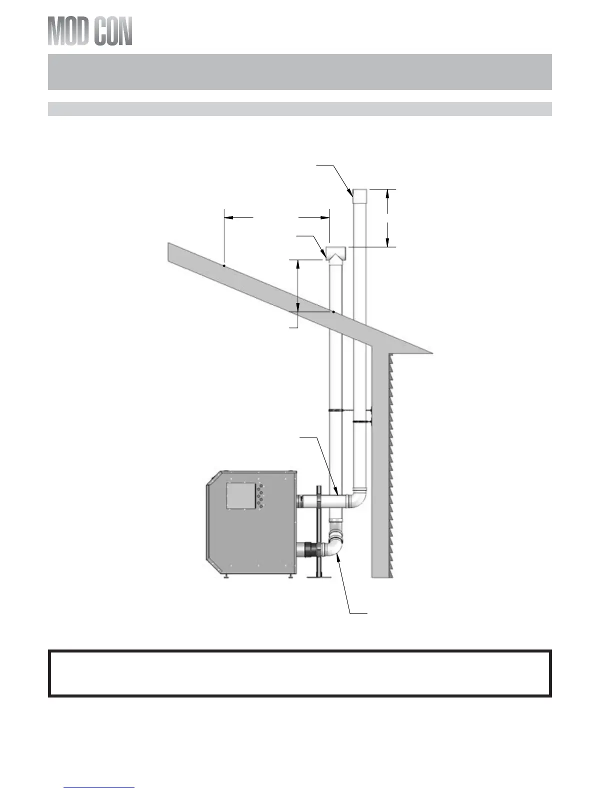
J. DIAGRAM FOR VERTICAL VENTING
GENERAL NOTE: All vent pipes must be glued, properly supported and the exhaust must be pitched a
minimum of a ¼" per foot back to the heater (to allow drainage of condensate).
NOTE: When placing support brackets on vent piping, the first bracket must be within 1 foot of the
appliance and the balance at 4 foot invervals on the vent pipe. The boiler venting must be readily
accessible for visual inspection for the first three feet from the boiler.
ROOF VENT WITH TEE (INTAKE)
AND COUPLING (EXHAUST)
PART 6: VENTING, COMBUSTION AIR & CONDENSATE REMOVAL (CONTINUED)