47
GAS-FIRED BOILER Boiler Manual
MOD CON Cascade Follower
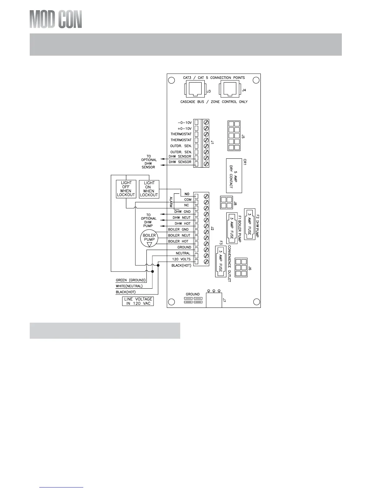
MOD CON CASCADE FOLLOWER PUMP
AND SENSOR WIRING
1. Connect the boiler pump to the terminals
labeled BOILER HOT, BOILER NEUT, BOILER
GND.
2. If you are using an indirect fired water tank
connected directly to the follower boiler
connect the pump for it to the DHW, HOT
DHW NEUT, and DHW GND terminals.
If you desire, an alarm bell or light can be con-
nected to the alarm contacts of the follower boil-
er. Optionally the normally closed alarm contact
may be used to turn a device off if the boiler
goes into lockout mode. The alarm contacts are
rated 5 amps at 120 VAC.
To connect an alarm device, connect the power
for the device to the ALARM COM terminal.
Connect the alarm device hot wire to the
ALARM NO terminal. Connect the neutral or
return of the alarm device to the neutral or
return of the power for the alarm device.
To connect a device that should be powered off
during a boiler lockout condition, follow the
same instructions as above except use the
ALARM NC terminal rather than the ALARM NO
terminal.
Note that in a cascade system the alarm output
of the Boiler addressed as #1 will also be active
if the master boiler has a lockout condition. The
alarm output of Boilers addressed as 2-7 will
only sound if a lockout condition occurs on that
specific boiler.
Fig. 8-4 LP-205-JJ1 Rev. 5/12/08
PART 8: FIELD WIRING (CONTINUED)