Horizontal Filter Dust Collector Owner’s Manual
Copyright© 2018 Mod-U-Blast®, All Rights Reserved
6
Clean
Air
Outlet
Compressed
Air Supp ly
Goyen
Valve
Hop per
Dirty
Air Inlet
Blower On
Normal Operation
Blower On
Filter C leaning
Operatio n
Goyen valves open
in sequence f rom top
to bottom knocking
dust out of the filters
Filters
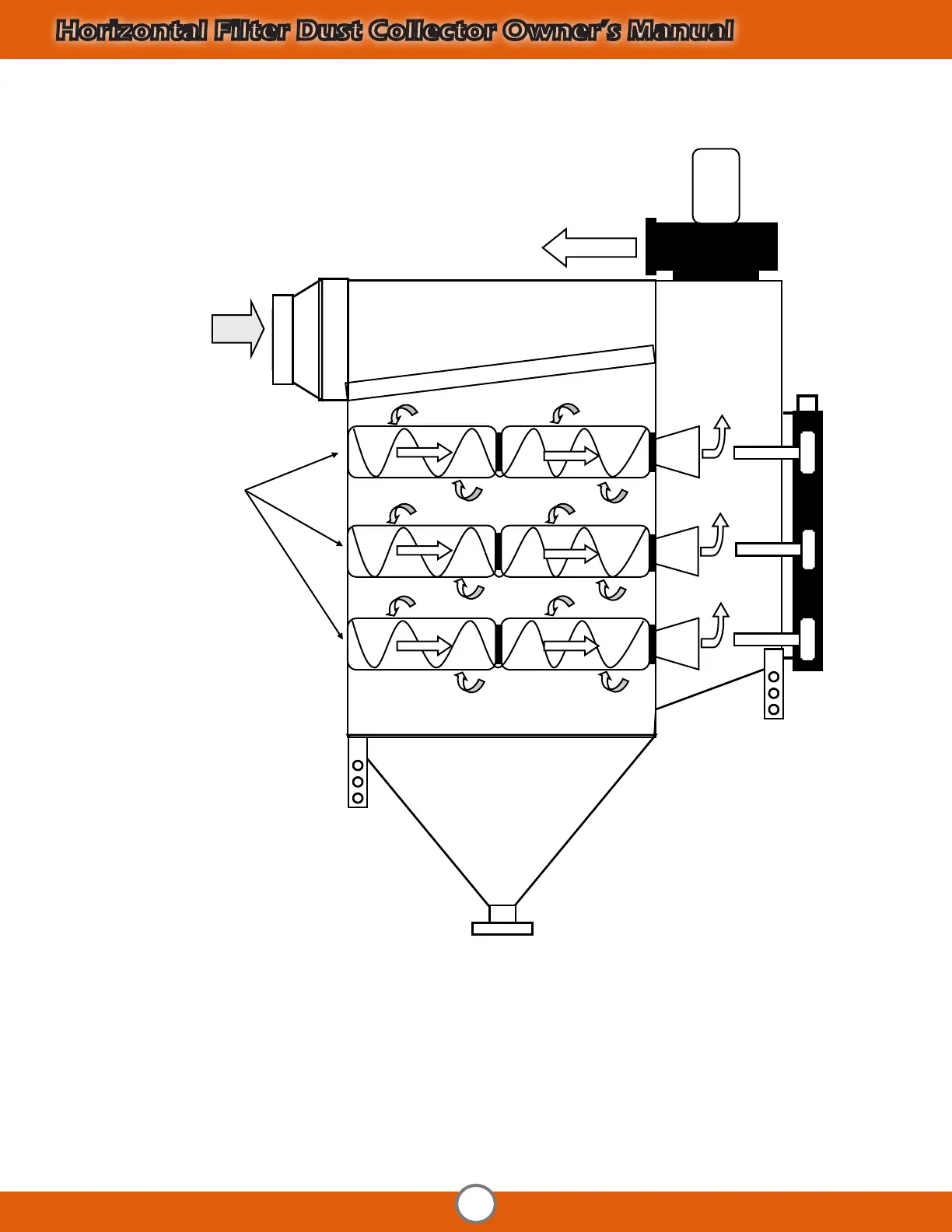
OPERATIONAL DIAGRAM
Throughout normal operation, the dust laden air enters the dust collector through the dirty a ir inlet ple num. The dirty air f lows
downward towards the hopper and the f ilters remove the f ine dust allowing clean filtered a ir to pass through the f ilters and out
past the blower f an.
Filter cleaning occurs when a signa l f rom the dust collector control pane l is sent to open the goyen v alves allowing a rush of air to
go through the filter bank knock ing the dust out of the f ilters and down into the hopper.
Dirty
Air Inlet
Clean
Air
Outlet
Operational Diagram
Throughout normal operation, the dust laden air enters the dust collector through the dirty air inlet plenum. The dirty air flows
downward towards the hopper and the filters remove the fine dust allowing clean filtered air to pass through the filters and out past the
blower fan.
Filter cleaning occurs when a signal from the dust collector control panel is sent to open the goyen valves allowing a rush of air to go
through the filter bank knocking the dust out of the filters and down the hopper.