C) Connect wire “V3 cathode” to V3 pin 1.
20
D) Connect wire “D” to T4 terminal 2.
E) Connect wire “E” to T4 terminal 5.
1 2 43 5
6
T4
Step 4 – Connect the Remaining Front Mount Components
Drawing 15 shows these connections.
A) Connect the other end of the 360Ω, 10W resistor to Pole B and now solder this connection.
Power Switch
Pole
B
Throw
B
On
Throw
B
Off
Throw
A
On
Pole
A
Throw
A
Off
B) Twist and connect two 20AWG green wires from the top lamp holder solder lugs to V4
pins 2 & 7 (do not solder the V4 ends, yet).
(It does not matter which wire goes to which lug, but
make sure not to connect the wires to the same lug).
D) Twist and connect two 20AWG green wires to the power switch “Throw A On” and “Pole
A” lugs and give them enough length to reach the rear panel of the chassis (about 10").
E) Connect the “Pole A” wire to T9 terminal 1 (do not solder this connection, yet).
C) Twist and connect TR1 brown & white wires to T9 terminal 3
(do not solder this connection, yet).
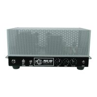
Note: Terminals are numbered from
left to right with mounting bracket
directed towards the viewer.
1 32
T9
Step 5 – Connect the Fuse Holder
Drawing 16 shows these connections.
A) Connect the “Throw A On” wire to the center lug of the Fuse Holder.
B) Twist and connect TR1 black & blue wires to the outer lug of the Fuse Holder
Center lug
Outer lug
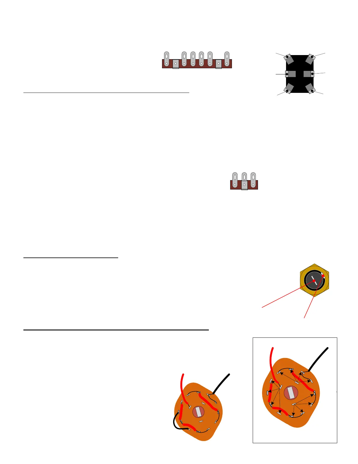
SECTION 7 – Connect TR2 to the Impedance Selector Switch
Please refer to Drawing 17.
A) Connect jumper wire from C2 to C4
(do not solder the connection at C2, yet).
blk
red
1
1
1
2
2
2
3
3
3
4
4
4
A
B
C
Switch terminal name convention
(Because this resistor will get hot, make sure to prop it up so that its body does not lean against any wires).
blk
red
1
1
1
2
2
2
3
3
3
4
4
4
A
B
C
jumper
Take your time and be careful not to break any pins on the
switch or unintentionally short neighboring connections
that should not be connected.