1
2
3
4
5
6
7
8
9
1
2
3
4
5
6
7
8
9
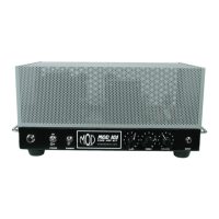
V2V1
328 VDC V1 (pin 1)
0 VDC V1 (pin 2)
Test Point DC Voltage
2.4 VDC V1 (pin 3)
320 VDC V1 (pin 6)
0 VDC V1 (pin 7)
V1 plate 1
V1 grid 1
V1 cathode 1
Name
V1 plate 2
V1 grid 2
1
2
3
5
6
7
8
V1 (pin 8)
V1 cathode 2
2.4 VDC
Voltages measured from test point to ground
with no signal, bias pot turned all the way
to cold and the following front panel
settings:
POWER: ON
STANDBY: (UP POSITION)
BASS: “0”
TREBLE: “0”
VOLUME: “0”
276 VDC V2 (pin 1)
68 VDC V2 (pin 2)
106 VDC V2 (pin 3)
254 VDC V2 (pin 6)
73 VDC V2 (pin 7)
V2 plate 1
V2 grid 1
V2 cathode 1
V2 plate 2
V2 grid 2
V2 (pin 8)
V2 cathode 2
106 VDC
1
2
3
5
6
7
8
Test Point DC VoltageName
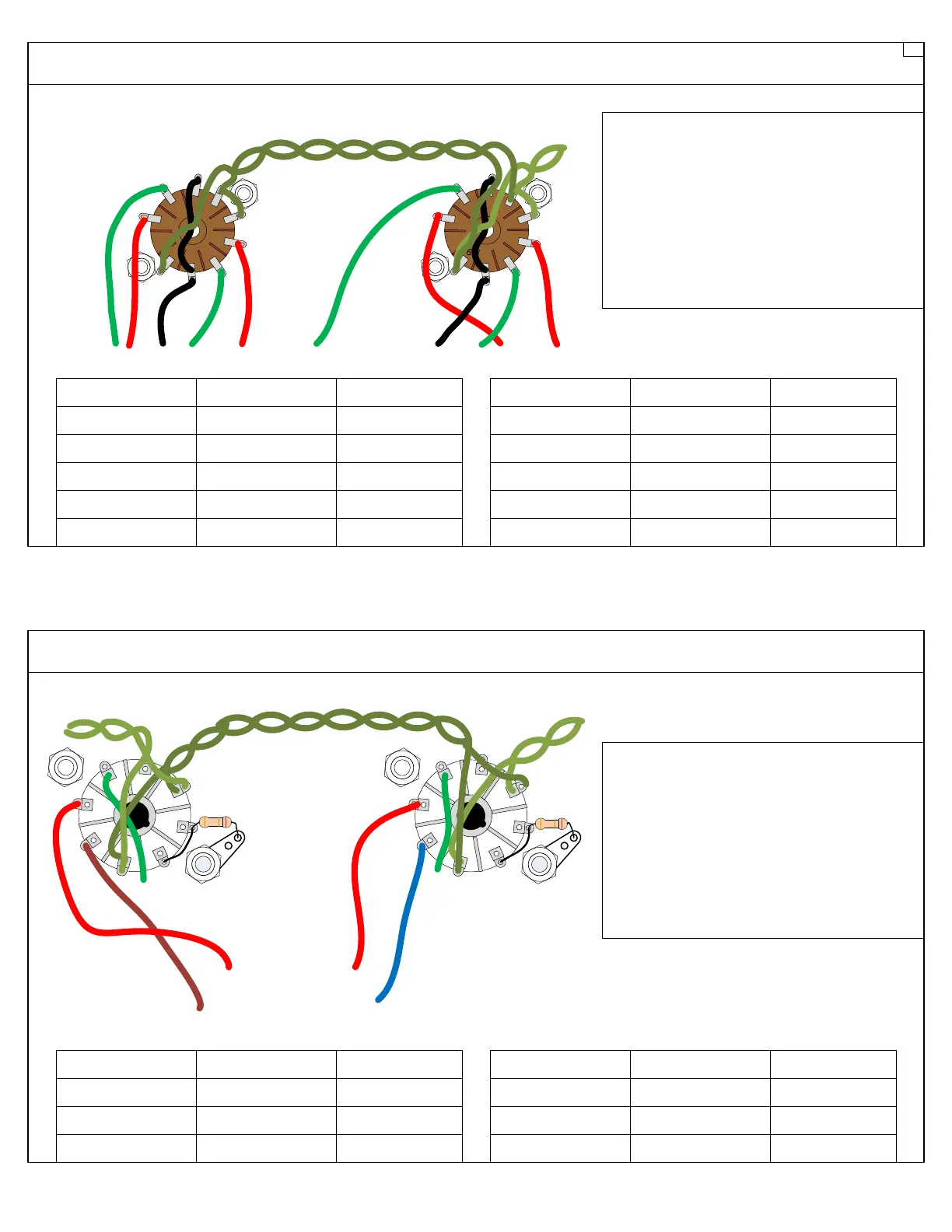
483 VDC V3 (pin 3)
470 VDC V3 (pin 4)
Test Point DC Voltage
-47 VDC V3 (pin 5)
V3 (pin 8)
V3 plate
V3 screen grid
V3 control grid
Name
V3 cathode
34 mVDC
487 VDC V4 (pin 3)
471 VDC V4 (pin 4)
Test Point DC Voltage
-46 VDC V4 (pin 5)
V4 (pin 8)
V4 plate
V4 screen grid
V4 control grid
Name
V4 cathode
36 mVDC
POWER TUBE ELECTRODES
PREAMP TUBE ELECTRODES
V4V3
1
2
3
4
5
6
7
8
1
2
3
4
5
6
7
8
1*
1*
3
4
5
8
3
4
5
8
Voltages measured from test point to ground
with no signal, bias pot turned all the way
to cold and the following front panel
settings:
POWER: ON
STANDBY: (UP POSITION)
BASS: “0”
TREBLE: “0”
VOLUME: “0”
See Assembly Drawing 22
See Assembly Drawing 22
6
A