12
T1
T2
22µF 350V
47
µ
F
3
5
0
V
22µF 350V
1
3
5
235
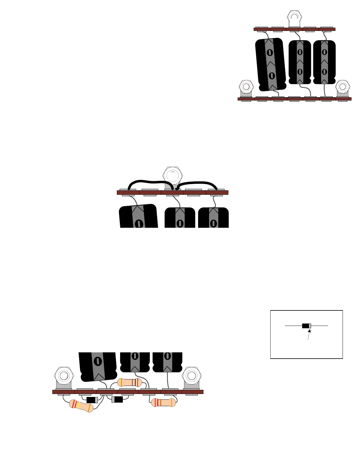
2) One 22 µF (350V) cap is soldered with negative end to
T1(1) and positive end to T2(2).
3) The other 22 µF (350V) cap is soldered with negative
end to T1(3) and positive end to T2(3).
Mount the three filter caps:
1) The 47 µF cap is soldered with negative end to T1(5)
and positive end to T2(5).
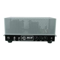
Connect jumper wires to filter caps:
T1
22µF 350V
47
µ
F
3
5
0
V
22µF 350V
5 1
3
1) Connect a short length of white wire (about 1.5") from T1(3) to T1(1).
When connecting the wire, you want to strip about ¼” of insulation off of each end to wrap around terminals.
2) Connect a short length of white wire (about 1.5") from T1(3) to T1(5).
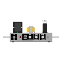
Connect T2 components:
1) Connect the 22K 1W resistor from T2(2) to T2(3)
T2
22µF 350V
47
µ
F
3
5
0
V
22µF 350V
2
20
K
22K
100
2
3
5
7
2) Connect the 100Ω 1W resistor from T2(3) to T2(5)
3) Connect the 220K 1W resistor from T2(5) to T2(7)
3) Connect one diode with the anode to T2(4) and cathode to T2(5).
3) Connect the other diode with the anode to T2(6) and cathode to T2(5).
cathodeanode
cathode side is
marked with a
silver band